VI-Suite v0.4 – Radiance Patterns

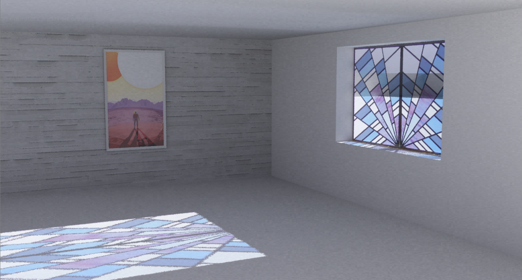
As of version 0.4.7 the VI-Suite can now use Blender’s UV image mapping system to create image based Radiance patterns. In the example Radiance rendering below an image texture has been mapped to the wall and picture to create a diffuse reflecting Radiance image pattern, and to the window to create a transparent one.

The video tutorial below details the process.

VI-Suite v0.3 – Tutorial 12 – Parametric Radiance Analysis

In this, probably the last version 0.3 video tutorial, I cover parametric Radiance analysis with LiVi. As parametric analysis in the VI-Suite is done using Blender’s animation system I cover the very basics of setting up animation in Blender and the export, simulation and visualisation of the Radiance analyses.
Although it will a while before I release version 0.4 I will soon start putting up sneak-peak videos of what to expect in the next version.

VI-Suite v0.3 – Exporting LiVi Data

A user asked me how to export the x, y, z co-ordinates of the LiVi sensor positions with the results to a comma separated file for further plotting or analysis. This capability will be enabled in version 0.4 with the “Results out” socket of the LiVi simulation node, but for now you can copy the python code below into Blender’s text editor and press the “Run Script” button at the bottom of the text editor window. This code will export the currently visualised results for the current frame to files in the project directory. These files are named ‘name_of_results_object.manualres’.

LiVi results data is stored within the mesh’s vertices and faces. To do this LiVi uses Blender’s Bmesh wrapper for the mesh data. So the first part of the code loops through results objects (line 3) creates a bmesh representation of each one (line 5) and transforms the bmesh (line 6) so that vertex and space positions are in global or world co-ordinates.

Line 7 designates either vertices or faces as the results points depending on the object ‘cpoint’ property (which is created on LiVi geometry export). Line 8 then checks that there are results available in the mesh and line 9 defines the cindex layer which stores whether a point in a mesh is a results point. Line 10 defines the resl layer which actually holds the results.

Line 11 generates the vertex or face positions for each results point and stores them in the variable posis. Line 12 and 13 then define the output file and writes the co-ordinates and the data to the file. The final line 14 clears the bmesh data from memory.

import bpy, bmesh, os
scene = bpy.context.scene
for o in [o for o in bpy.data.objects if o.type == 'MESH' and o.get('cpoint') and o.lires]:
    bm = bmesh.new()
    bm.from_mesh(o.data)
    bm.transform(o.matrix_world)
    geom = bm.verts if o['cpoint'] == '1' else bm.faces
    if geom.layers.float.get('res{}'.format(scene.frame_current)) and geom.layers.int.get('cindex'):
        cindex = geom.layers.int['cindex']
        resl = geom.layers.float['res{}'.format(scene.frame_current)]
        posis = [v.co for v in bm.verts if v[cindex] > 0] if o['cpoint'] == '1' else [f.calc_center_bounds() for f in bm.faces if f[cindex] > 0]
        with open(os.path.join(scene['viparams']['newdir'], '{}.manualres'.format(o.name)), 'w') as resfile:
            resfile.write('\n'.join(['{0[0]}, {0[1]}, {0[2]}, {1}'.format(posis[gi], g[resl]) for gi, g in enumerate(geom) if g[cindex] > 0]))
    bm.free()

Indentation in Python is important so make sure the code in the Blender Text editor window looks like the screenshot below.

manualres

Anatomy of a node

One of the simplest nodes in the VI-Suite is the location node. The location node defines the location of the building to be analysed in terms of latitude and longitude, and is a required node for Sun Path, Shadow Study, Wind Rose, LiVi and EnVi analyses.

The image below shows the Python code listing for the location node.

Basic node Python code

A node in Blender is an instance of a Python class and so the code begins with a class definition that locates the node within the ‘VINodes’ node tree.   Lines 2 to 5 identifies the name, label and icon of the node.

Lines 7 to 13 define some parameters associated with the node. Parameters are important as they not only hold values, but also create user interface elements to allow the user to alter their values. Parameters for the location node include the latitude and longitude values.

A Blender node has a number of built-in functions, but as a node is an instance of a class we call these built-in functions methods, that are called during the ‘life’ of the node. When a node is created by the user the ‘init’ method is executed and lines 15 to 21 defines what happens when this occurs. In this method a property is associated with the node called ‘nodeid’ which contains the name of the node and the name of nodetree that the node sits in. An external function is run called ‘nodeinit’ which creates some platform specific parameters the VI-Suite uses, and finally an output socket is created.

Whenever the user changes the socket connections of this node the method ‘update’ is executed, which is defined on lines 23 & 24. When the update method is executed it in turn executes an external function called socklink that checks if the socket on the other node we are connecting the output socket of this node to is the same colour. If so the connection is made, if not the connection is not made. This helps make sure the user does not construct node connections that would result in an error.

The final method we use here is the draw_buttons method where we can define the user-interface presented by the node. In this function some of the parameters of the node defined earlier are presented. For example the ‘loc’ parameter is defined as a Blender EnumProperty. An EnumProperty in Blender basically represents a list, and the loc parameter has two entries in its list: A ‘Manual’ entry and an ‘EPW’ entry. When we include the ‘loc’ parameter in the draw_buttons method Blender automatically creates a drop-down menu interface for this parameter. Similarly, the latitude and longitude parameters are defined as FloatProperties, which represent regular numbers. When these are included in the draw_buttons function, Blender creates boxes that allow the user to manipulate these numbers.

If ‘EPW’ is selected in the ‘loc’ menu then an EnumProperty drop-down menu is displayed to select the desired EnergyPlus weather file. Weather files with an .epw or .EPW extension should be placed within the vi-suite/EPFiles/Weather directory. After adding a weather file Blender needs to be restarted to see the new file.

The short video shows how the location node functions.

VI-Suite location node from Ryan Southall on Vimeo.

Installing the VI-Suite

First get hold of a copy of the most recent version of Blender (2.69 at the time of writing) from http://www.blender.org and install it. If this is the first time you have used Blender open it and select the ‘File – User Preferences’ menu item. The settings window will appear and for now simply click the ‘Save User Settings’ button in the bottom left corner. This makes sure that the Blender configuration directory is created on your system.

On a Windows 7 PC this directory can be found at  C:\Users\your_username\AppData\Roaming\Blender Foundation\Blender\blender_version

On a Mac it can be found at /Users/your_username/Library/Application Support/Blender/blender_version

And on an Arch Linux machine can be found at /home/your_username/.config/blender/blender_version

Other operating systems may vary but this directory should be created somewhere similar.

Within this folder create a directory called ‘scripts’ and within this a directory called ‘addons’.

For those comfortable with the command-line navigate to the ‘addons’ directory above and checkout, with Mercurial, the VI-Suite code from the Google Code repository with the command:

hg clone https://code.google.com/p/vi-suite/

This should place a ‘vi-suite’ directory within the addons directory.

Alternatively, a zip file containing the VI-Suite code can be downloaded from https://code.google.com/p/vi-suite/source/list by clicking the download zip button just above the list of code changes. The directory within the zip file should be renamed to ‘vi-suite’ and moved to the ‘addons’ directory.

Upon starting Blender the VI-Suite should be registered as an available add-on. The video below shows how to activate this add-on within Blender.

Activating the VI-Suite from Ryan Southall on Vimeo.

Introducing the VI-Suite

The VI-Suite is a set of environmental analysis tools presented to the user as a set of connectible ‘nodes’ within the 3D content creation suite Blender. Blender nodes have traditionally been used for the application of a sequence of post-production tasks on rendered images. More recently they have been used to define materials for Blender’s new physically based rendering system, and very recently nodes, and the nodetrees that they sit in, have become user programmable with Blender’s scripting language Python. It is this latter development that is leveraged here.

I have previously written two Blender based interfaces for environmental analysis: LiVi, for lighting simulation with Radiance, and EnVi for energy simulation with EnergyPlus. As these interfaces became more advanced it became increasingly difficult to see how I could easily manage communication between these types of analyses e.g. using accurate solar radiation data from LiVi in the temperature calculations of EnVi. It also became difficult to envisage how the data generated by these analyses could be used to flexibly manipulate geometric form for environmental parametric and generative design studies. This is where a node based system comes in very handy. By having analyses broken down in to a set of modular nodes, the user can connect these nodes as they wish, for example modifying window size according to solar radiation or light levels and density of parametrically generated shading forms.

When combined with ancillary nodes like sun path and wind rose generators, shadow study node and glare analysis nodes the VI-Suite becomes a powerful holistic tool to explore interconnections between building form and performance.