Initial task
We were tasked with creating a simple circuit on a breadboard that used an input, output and a capacitor. We also had to plan the circuit using Fritzing software.
Fritzing!
The Fritzing software is a good little package for designing circuits. It allows you to piece them together using realistic representations of the components all connecting via a breadboard or the more traditional wiring diagram using symbolic representation for the components. Each component can be dragged into position and the values i.e. a resistors resistance can be adjusted accordingly.
Unfortunately it can’t be used to test if a circuit will work but it does link directly to manufacturing and you can purchase the PCBs that you’ve designed directly through the software.
It can be downloaded free here: www.electroschematics.com/fritzing-software-download
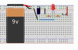
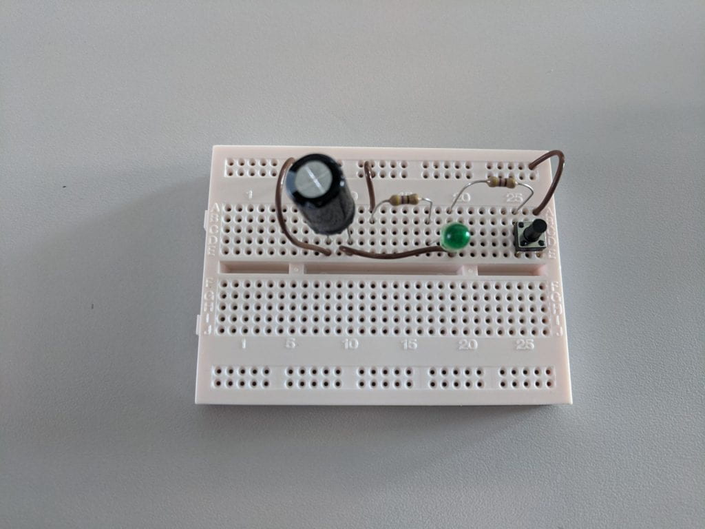
The circuit was powered with a 9v battery. It had a button (input) which when pressed illuminated the LED (output). There is a capacitor in the circuit that makes the LED slowly dim instead of immediately turning off when the button is no longer pressed.
Using Fritzing software I first made a visual and technical wiring diagram:

Fritzing visual diagram

Fritzing wiring diagram
The circuit was powered with a 9v battery. It had a button (input) which when pressed illuminated the LED (output).

The capacitor meant that when the button was released the LED stayed illuminated for a short time, as seen in the below video.

Unfortunately this circuit didn’t work as intended – the capacitor didn’t have the same effect as it had with the previous circuit.
Finally by adding a capacitor for each LED I was able to get it to work where each LED slowly dimmed after being illuminated.

On the breadboard it looks quite messy but it is easier to follow the circuit when made in Fritzing. The colour of the wires corresponds with the colour of the LEDs

Second task
The second task was similar in that it required us to create a circuit that included an input and and output. The main difference was that rather than using a breadboard we used a pre-made PCB and soldered the components on.
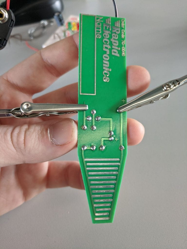
I was using a pre-made Moisture Tester kit that is produced by Rapid Education, available here. The kit came with all the components and a wiring diagram to follow. The moisture tested worked by having many open contacts at one end that when placed in soil with sufficient moisture content the contacts would be connect and close the circuit making the LED illuminate. This would allow the user to know if the soil was dry and whether it needs watering.


I’ve luckily got previous experience with soldering and following wiring diagrams so I didn’t find this too tricky. I also used the Fritzing software to recreate the circuit of the moisture tester:
Note. The way the moisture sensor works is that it basically has many open contacts that the moisture can complete the circuit across, there isn’t a component for that in Fritzing so I used a switch (S1) as a place holder. Also, for this circuit the power supply is actually 9v!!
This kit suggested that a 9v battery be used to power the circuit but I decided to use a DC power suply connected by crocodile clips, as pictured.
This meant that I need to learn how to use a dc power supply, I found this video very useful – it’s long but by far the best I found, skim through it to get the gist.
