Week 3 – How to get a computer to control your cutting.
As ever, this project started with a look at the Fab Academy notes HERE and watching the week 3 lecture HERE where parametric computer controlled cutting is introduced by professor Neil Gershenfeld.
Here are my examples of parametric design

I have set constraints in this Solidworks sketch so that all lengths annotated ‘A’ are equal, all lengths ‘B’ are equal and all lengths ‘C’ are equal. This means that when the length dimensions are changed they all change together, as seen in this short clip.
The task for this week was to design, lasercut, and document a fun, parametric press-fit construction kit for kids, accounting for the lasercutter kerf, which can be assembled in multiple ways. The kit should be controlled using a two parameters: for a) the material thickness, and b) the kerf width. We also had to make a sicker/label for the cardboard kit that can be cut out using the vinyl cutter in the FabLab.
This is a good example of the type of thing that could be made: http://fab.cba.mit.edu/classes/863.12/people/salzberg/week2.html
The idea I have is a modular plant/tree thing that has 3d stems using the laser cutter to create scored fold lines and 2d leafs that can fit into the stems.
I started by making the sticker
Dr Covill has produced a very useful guide (available here) on how to produce a sticker using the vinyl cutter. I’ll also document my process below.
As I’m going to make a plant inspired kit I found a free to use image of a leaf online and opened the raster (pixel-based) image in Adobe Illustrator. Looking like this…

Raster image in Illustrator
Then used Object > Image Trace > Make and Expand to convert the image to a tracing object with vector paths that can be edited. Here’s the result…

Edited to have vector paths
This can now be saved as an .ai file to be used with the vinyl cutter or saved as a .dxf and used with the laser cutter.
Cardboard Kit
I came up with a design for a flat kit that would make a small tree when assembled.

cardboard tree kit assembled
This kit is made up of 3 main parts:
- The trunk which is the part that folds together to make a box section.

The stem section before being folded

The stem folded
- The base and branches which are made of one single piece that is folded 90°. I designed it to look like roots or branches.

The flat piece that when folded make the base or branches
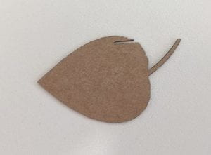
- The leaves – this leaf was the same one I used to create the .ai file and the sticker. I exported it from Illustrator as a .dfx and used Solidworks to scale it down. The only adjustment I made was to add a slit so that it could attach to the branches or trunk.

The parts of the kit are parametrically linked in that the slot gap for them to connect is associated across all parts and the dimension of the slot is related to the material thickness. So when I experimented with material thicknesses I only had to change the width of the slot to reflect the material and the kerf of the machine and the geometry of each part updates to provide an interference fit between them.
Initially I made this kit from 2mm corrugated card:

2mm test pieces
The corrugations of the 2mm card made for uneven folds so I used 0.5mm card.
It was hard to find the right settings on the laser cutter to work with the 0.5mm card so that the fold lines were scored but not cut all the way through. Normally this would be done by selecting ‘etch’ as the cut type but this resulted in cutting the card all the way through.

A failed attempt to get the laser cutter settings correct
Through testing I found that on one specific laser cutter [insert model here] the optimum settings were: ‘0.25 card 50W’ (with the cutter set at 100W) and make any lines you want scored as ‘kiss cut’.
The final kit is very compact. It has 1 trunk piece, 4 branch/base pieces and 8 leaves.

This is the final packaged product
Still to do:
Vinyl cut sticker and make a small box for the parts.
