Title: Development of open source bicycle testing machines
Authors: Covill, Blyth, Hardy, Mohamed, Pissara, Smith, Tanaka.
Abstract – do this later
Background Methods Results Discussion Conclusions Future work
Introduction
This wiki is designed to form the basis of three things:
- an open source online platform for the development of test rigs to perform static and fatigue tests on welded/brazed joints, bicycle frames and other components.
- As such, this wiki should include all design files and detailed instructions on how to do things.
- an academic publication (e.g. journal of machines, or journal of sports engineering and technology) relating to this project which the XE700 and XE636 students can contribute to
- As such we need to include academic rigor, critical evaluation, technical detail/theory/analysis and good referencing!
- content for the XE636 and XE700 reports
Literature review- do this later
- review relevant mechanics and fatigue theory
- explain BS EN ISO 4210
- review relevant work existing test benches
- review other relevant machines:
- review relevant work on bicycle testing and analysis
- review relevant work of bicycles FEA
- review relevant/similar work on pneumatic, control, safety systems
- other sections?
Pneumatic actuation system
Electronics and logging systems
Control systems
Safety systems
Frame design for testing welded/brazed joints
The frame has been designed to accommodate two main types of welded/brazed joints:
- a 63 degree configuration to test what would be a realistic toptube-downtube junction
- a 90 degree t-joint configuration that is a standard
We have decided to test tubular joints, since they are the types of joints created by bicycle frame builders, and so they represent the reality of what happens with bicycle joints – including all the specific challenges and benefits that comes with this.
The Figure below shows a section view of the original 63 degree configuration with the welded tubes, holding arbors, mounting plates and , and here is a zip file with the MAIN-ASSEMBLY-2060.
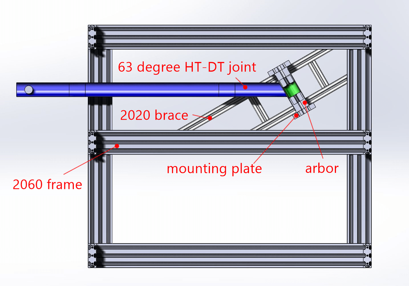
Figure: A section view of the 63 degree configuration for the welded/brazed joint testing machine. The machine has a 2020 brace included here to allow for the 63 degree configuration to be tested, but this can be removed and replaced with just the mounting plates positioned on the top two horizontal beams of the 2060 frame.
Frame design for BS EN ISO 4210:6 horizontal forces test
Open access development of bicycle testing machines – do this later
Describe how things are now made available to others (website/github etc)
Conclusions – do this later
Future development
From Darren
With this we can control (vary) the air pressure output to each port on the manifold (I suggest a 6 valve setup – manifold).
e.g. we can have up to 6 cylinders (initially – 3 – one for the frame and 2 for the pedals) and supply different air pressures to each cyclinder PER CYCLE with load cells feeding back/limiting the forces (presumable using PID – hence the work on the proposal 2 – stepper rig) to each part of the bike frame.
The potential fatigue test options in the future would be endless and for us as students, demonstrate proper industrial control.
Regulator:
https://uk.rs-online.com/web/p/products/1961204/
£548.26 + Vat £109.66 = £657.92
Manifold:
https://www.youtube.com/watch?v=mHZks-EtJ_E
£232.76 inc vat
Valves:
https://uk.rs-online.com/web/p/pneumatic-solenoid-pilot-operated-control-valves/4943226/
£77.36 inc vat each (we may be able to use the two we have already so will need 1 extra eventually or more if we decide on more fatigue test points)
SMC products
There are new manifolds available from SMC that aren’t listed on RS yet which may work out cheaper or better so a bit more research and thought will be needed prior to submission of an order
From Ryoma:
3/2 solenoid valve NO: https://tameson.co.uk/pneumatics/directional-valve/electrical-actuated/3-2-way/mvsc1-220-3e1-no-dc24-d-g-g1-4inch-24vdc-3-2-way-no-solenoid-valve-1p5-8bar.html
This solenoid valve basically shuts the air flowing through to the 5/2 solenoid valve, and also to de-energized all the trapped air in the cylinder. So whenever displacement sensors detect the overshoot, it automatically stops the cylinder moving. Plus keeping the pressure between the cylinder to the solenoid valve is very undesirable as looking at the safety side.
I got an idea from this video(2:26 at video)
https://youtu.be/pK6gTlH8rHI
RS store has Normally closed 3/2, but not Normally open one unfortunately.
If I use NC, It needs voltage run thought always to keep the valve open, which causes the heat on solenoid.
Another thing! This is for the displacement sensor.
Linear potentiometer (5.28£)
https://uk.rs-online.com/mobile/p/potentiometers/2346550/
