This week we were tasked with learning the basics of electronics design. We started off with some theory and then quickly moved into using a breadboard to prototype a simple circuit. 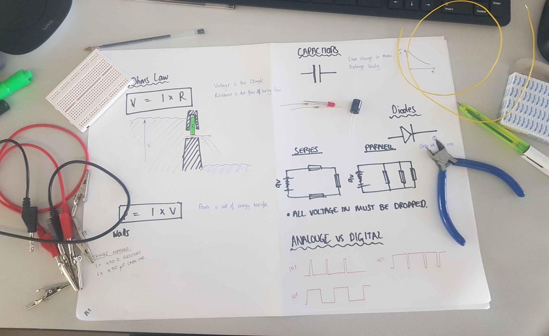
For our first circuit we had to make a circuit with an LED and a Capacitor in Parallel with one another. The purpose of this circuit was to show that the Capacitor stored charge and how it discharged it. The LED came on when the button was pressed, and then slowly faded out to off again when the button was released. This is because while the button was on, The Battery powered the capacitor and the LED and the capacitor was charged up. When the button was released, the charge stored in the capacitor was then the only power source in the circuit so it discharged its energy to the LED
I had never used a breadboard before and I found the way the holes are connected interesting: the top and bottom two rails are connected horizontally, then the two middle blocks are connected vertically, I soon got comfortable using this system to Connect my components and moved on the using a through hole component Printed Circuit Board (PCB). This board required the use of a soldering iron to attach the components so is not as suitable for prototyping as a breadboard but you do end up with a smaller and more durable circuit using it.
I originally tried to solder in the LED and the Transistor in first because I was worried about making sure they were in the right orientation. However, because these components were also the largest ones, it made it tricky to get at the other components and to solder on a flat surface. This meant I decided to take the bigger components back out and do the resistors first. I also realised that on a smaller circuit with more components, it would be very important to solder from the middle outwards so that you can always get at the base of the component from outside. As it was, this wasn’t a huge problem due to the simplicity of the circuit.
I used a Power supply to control the Voltage to the Circuit. The Circuit had a 9 Volt battery connector so the maximum voltage I used was 9 Volts. I did try varying the voltage though and found the brightness of the LED would increase with the amount of voltage supplied. This lined up with the idea of the voltage being the pushing power (or the O0mph!) of the circuit. More Oomph means more Light. I also used the multi-meter (Machine on the left of the photo) to check the resistance of components in the circuit.
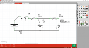
I also tried using Fritzing to design the circuit I had just made. This was useful to help me get a better grasp of all the symbols and the way a circuit diagram works. Fritzing comes with a large range of electrical components that you can just drag and drop into a circuit diagram. Here the image of the component changes into its symbol which has helped to learn the circuit symbols. Fritzing also allows you to output the circuit diagram to a PCB design. 
It also has a function where you can directly output this circuit board to their web store and they will quote a value to produce one of these boards. to start off with, the quoted price of this board was around £30 because it was so spaced out and the board it would be printed on would have been huge. I decided to have a play with the layout of these components reasoning that the smaller I could make the layout of them, the cheaper and more usable the circuit would be.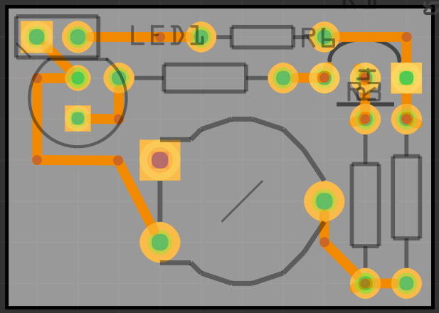
This is the final PCB as small as I could make it. The price of this board was roughly £5.40 per unit compared to the original with a price of near £30. I was careful to make sure none of the wires overlapped and that all the components have enough room to be soldered on without overlapping one another.
