17/06/2019: 3D Printable Clamps
I am using 3D Printable Over-Clamps for my machine. Originally the screw would thread into the plastic, I have now redesigned the T-Nut to have a hex recess underneath to fit an M3 bolt.
This is not only more durable, but also means that wing-nuts can be used for tightening down the clamp. I have made the files available on GrabCAD.

14/06/2019: CNC Assembly
This is the final design of the CNC machine. I am now able to begin milling some test parts which will identify any issues which need sorting/re-designing.

Plans for the future:
- Extraction System
- Housing (laser cut)
- Dust Shoe
- LCD for digital readout, following this guide: https://wiki.shapeoko.com/index.php/LCD_on_GRBL
- Addition of a ‘Probe’ on the z axis for height setting.
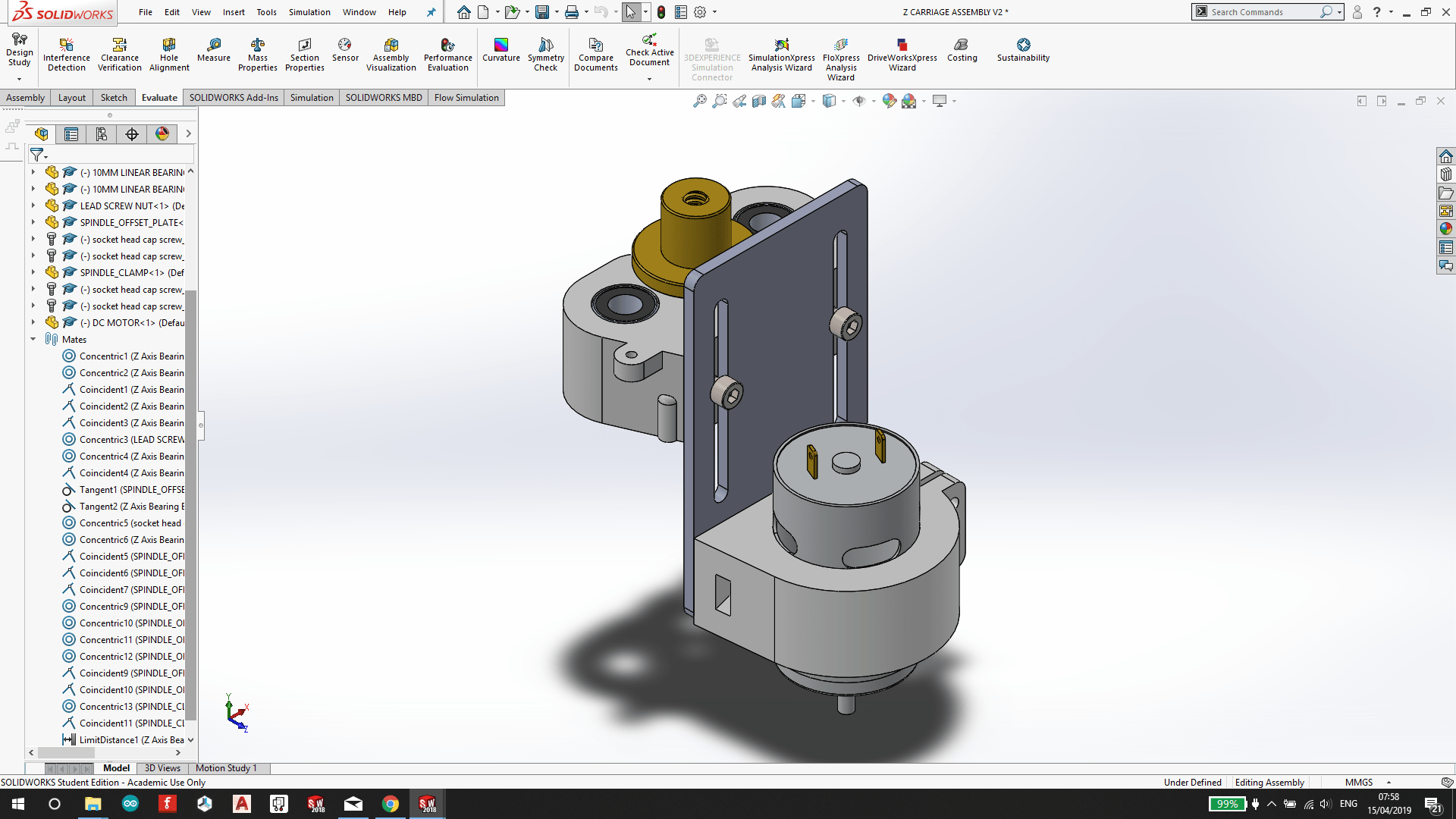
14/06/2019: Adjustable spindle height setting
Previously, the spindle clamp and Z-axis bearing block was one 3D printed part. The spindle clamp now mounts to a sloted lasercut MDF plate, allowing the height of the spindle to be adjusted.
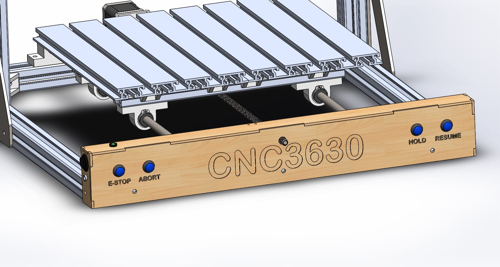
14/03/2019: Control Panel
I have added a control panel which mounts to the front cross member of the frame. The panel will be laser cut from 3mm MDF.
The panel has a DC socket and a main power switch, along with an indicator LED. There are also four push buttons which do the following: Hold, Resume, Abort, Emergency Stop.


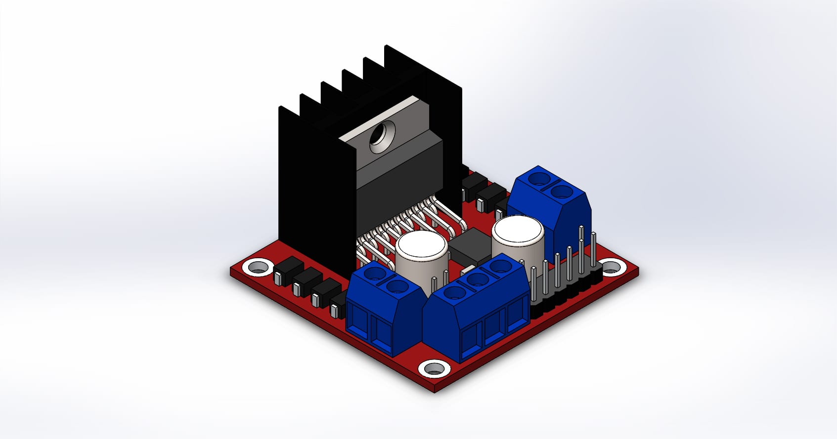
12/03/2019: Spindle Motor Driver
The spindle motor will be driven by an L298N 2-channel H-bridge driver. I have purchased the motor driver module module for £2.85, its available here.
I have modelled the module in Solidworks so that I can use the dimensions for designing mounts and a housing for the electronics.
I have made the model available on GrabCAD: https://grabcad.com/library/l298n-h-bridge-motor-driver-1
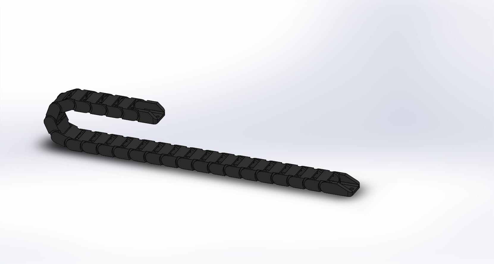
05/03/2019: Cable Drag Chain
I have designed a cable drag chain which will run across the gantry to the X-Carriage assembly. This assembly will be 3D Printed. I have made the Solidworks files available on GrabCAD.
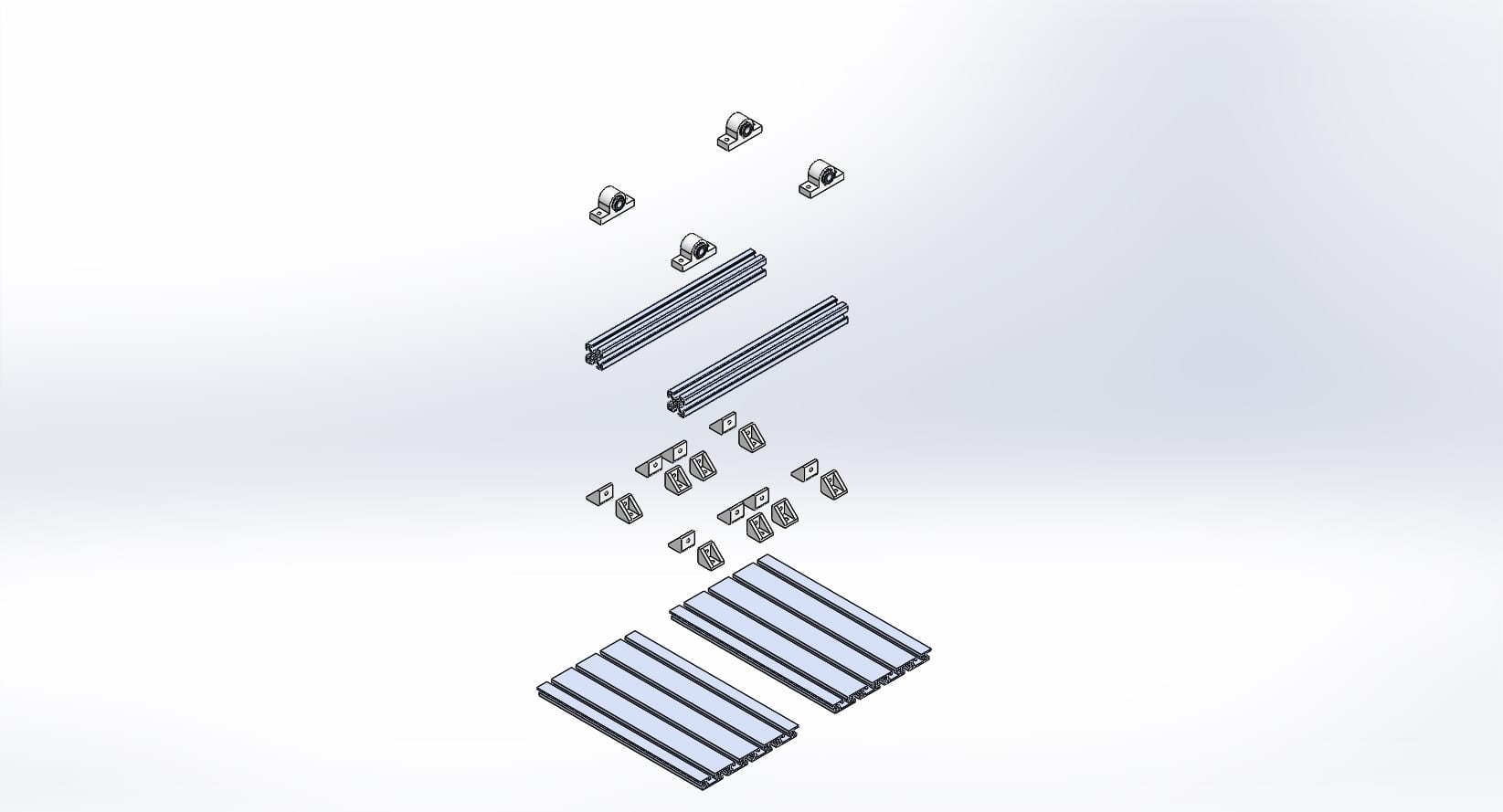
26/02/2019: CNC Bed Design
The CNC bed plate consists of two lengths of T-Slot plate to make a total size of 300 x 360mm. The two plates are held together with two lengths of 30×30 extrusion. A variety of 3D printed fixtures are also part of the assembly.

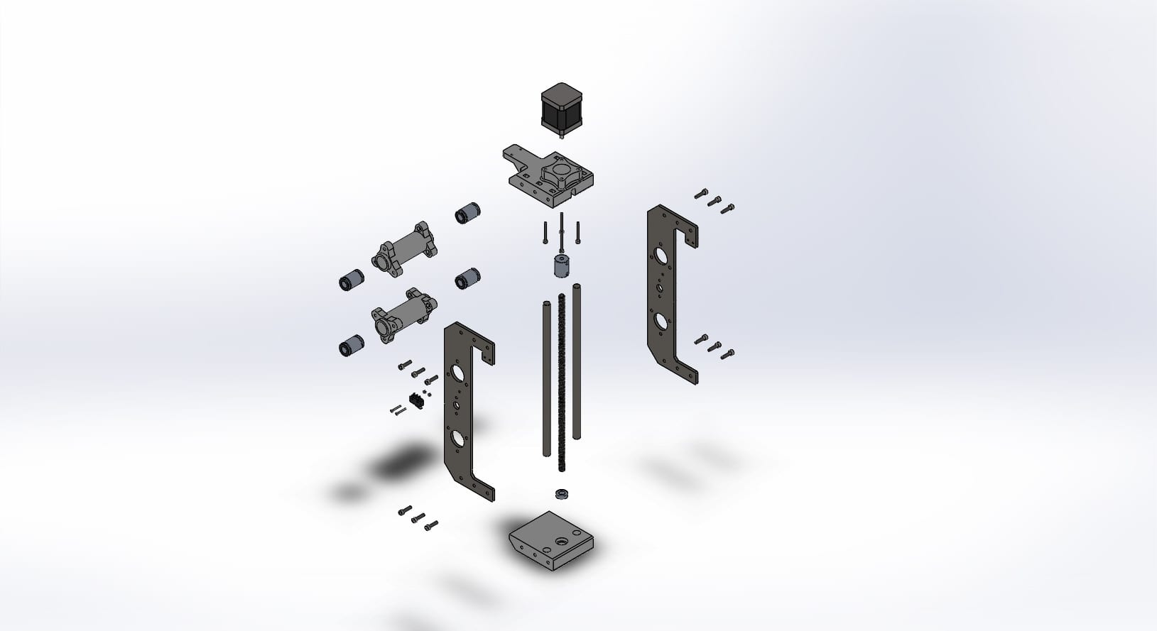
21/02/2019: X-Carriage
The X-Carriage design is pictured below. This assembly will slide in the X direction along two steel guide rods. It also carries the Z-axis, which will slide long the two vertical steel rods, controlled by the NEMA17 stepper motor mounted at the top of the assembly.

14/02/2019: The design so far
My machine is based upon a low cost CNC kit available from Banggood.com, like the one shown in the picture below:

I have used a similar frame design but scaled up to fit a larger bed plate. The design utilises 30 x 30mm aluminium extrusions, and will be held together with a combination of 3D printed and CNC Plasma cut brackets.

