14/06/2019: Spindle assembly
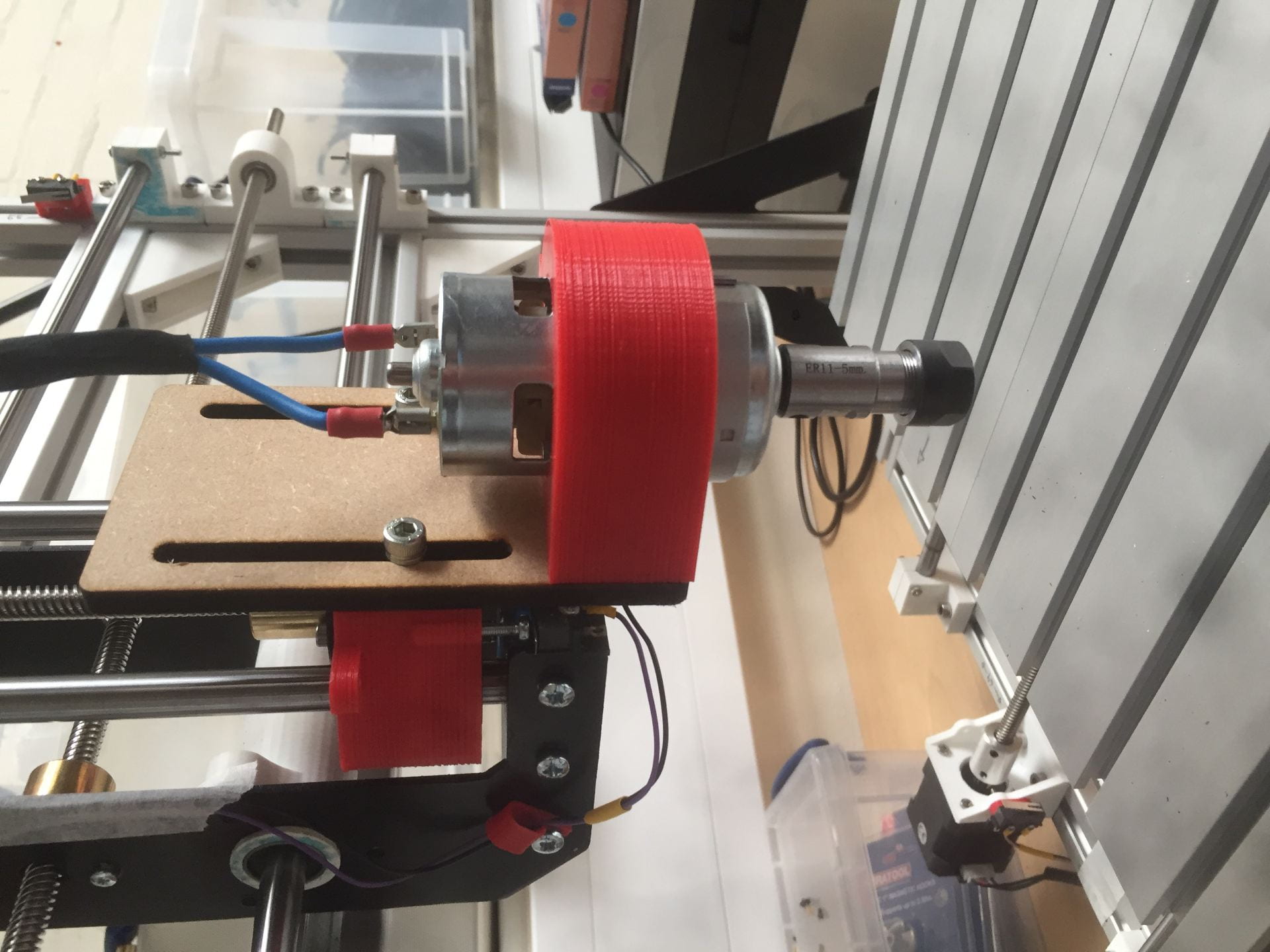
The final part of assembly on my CNC machine is the Z-axis and spindle.
The spindle clamp has been modified to have additional adjustment in the Z direction. A sloted MDF plate can be raised or lowered, then clamped in place with two M5 bolts. I may upgrade the MDF plate to steel.
I now also have a chuck and collet set on the spindle motor, the collets can hold milling bits from 2 – 11mm.
The image below shows the stock (foam) mounted to a piece of MDF with double sided tape. The MDF is then clamped to the bed plate with 3D printed over-clamps.

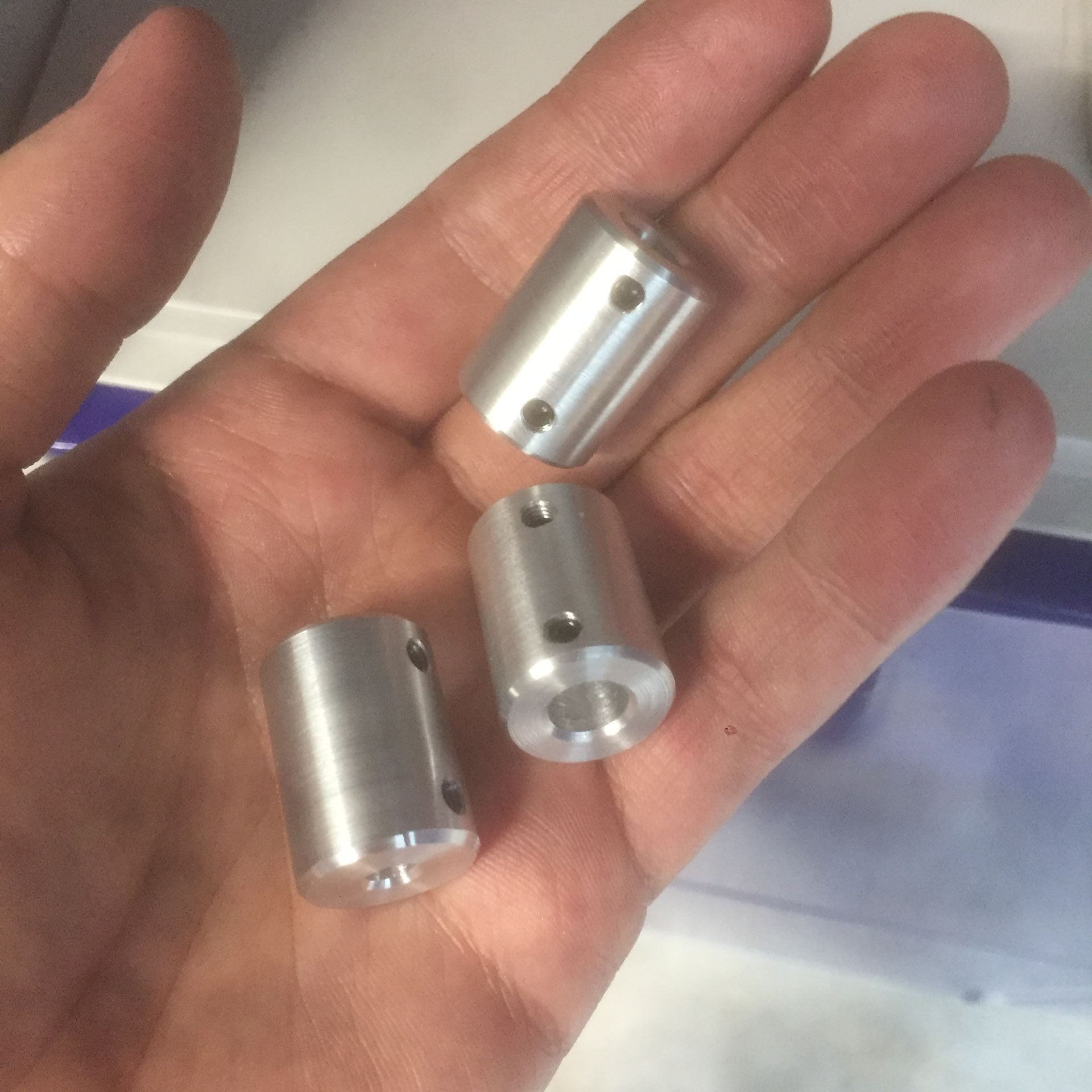
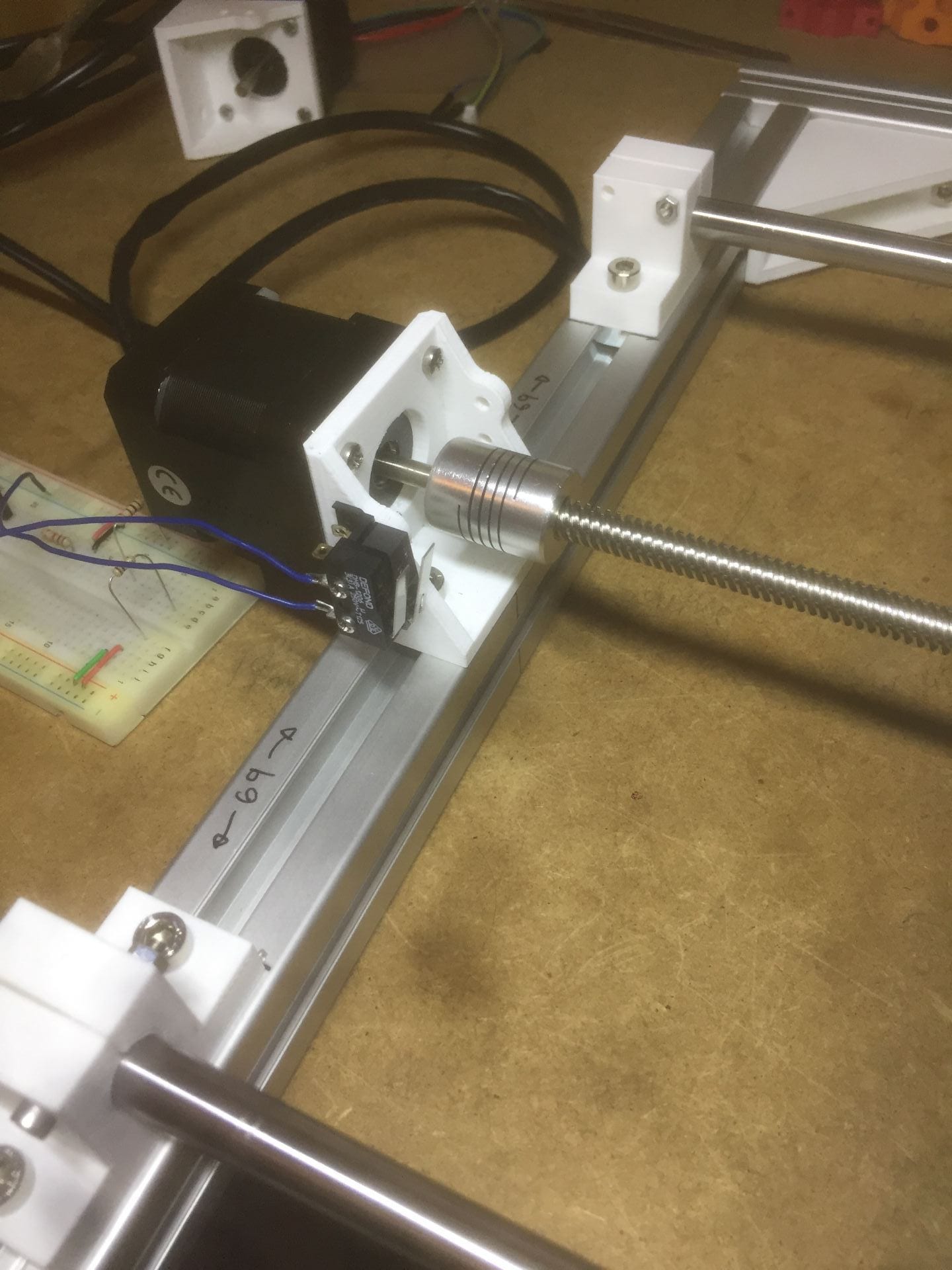
23/04/019: Shaft Couple
Ive made my own shaft couplings for the 5mm stepper motor shaft to the 8mm lead screw. Turned on a lathe from 20mm aluminium bar. 2x M4 grubscrews are in each coupler.
The shaft couplers i bought from ooznest arre ‘flexible’ which caused axial movement of the leadscrew by up to 2mm.

21/03/2019: Spindle Clamp
The spindle motor is clamped by a 3D printed component. two bearings are pressed into the clamp to slide along the z-axis guide rods.

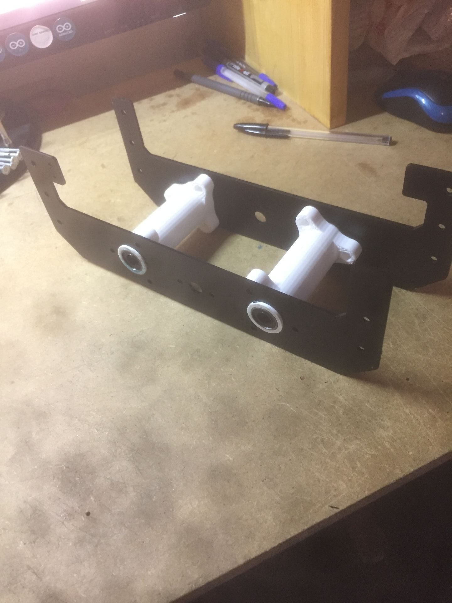
19/03/2019: Z-Axis Assembly
The Z-axis assembly is constructed with two steel plates (now painted black) and some 3D printed parts which hold the guide rods, bearings, and stepper motor.

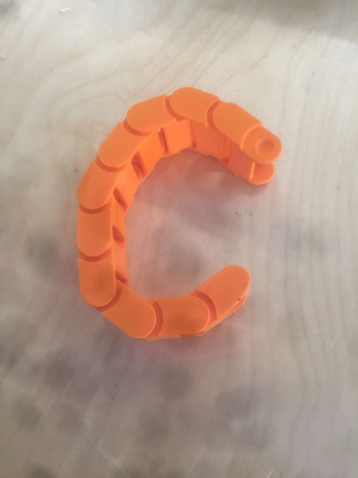
15/03/2019: 3D Printed Cable Drag Chain
The cable drag chain will run along the top of the gantry carrying the wiring to the Z-axis stepper motor and spindle motor.

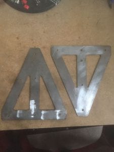
14/03/2019: Plasma Cut Steel Plates
2.8mm steel plates are used to support the gantry and used in the assembly of the Z-Axis. The Solidworks designs where converted to .DXF in order to be CNC Plasma cut. The holes where drilled after plasma cutting.


10/03/2019: Gantry Assembly
My design consists of a fixed gantry which supports the x-axis assembly.


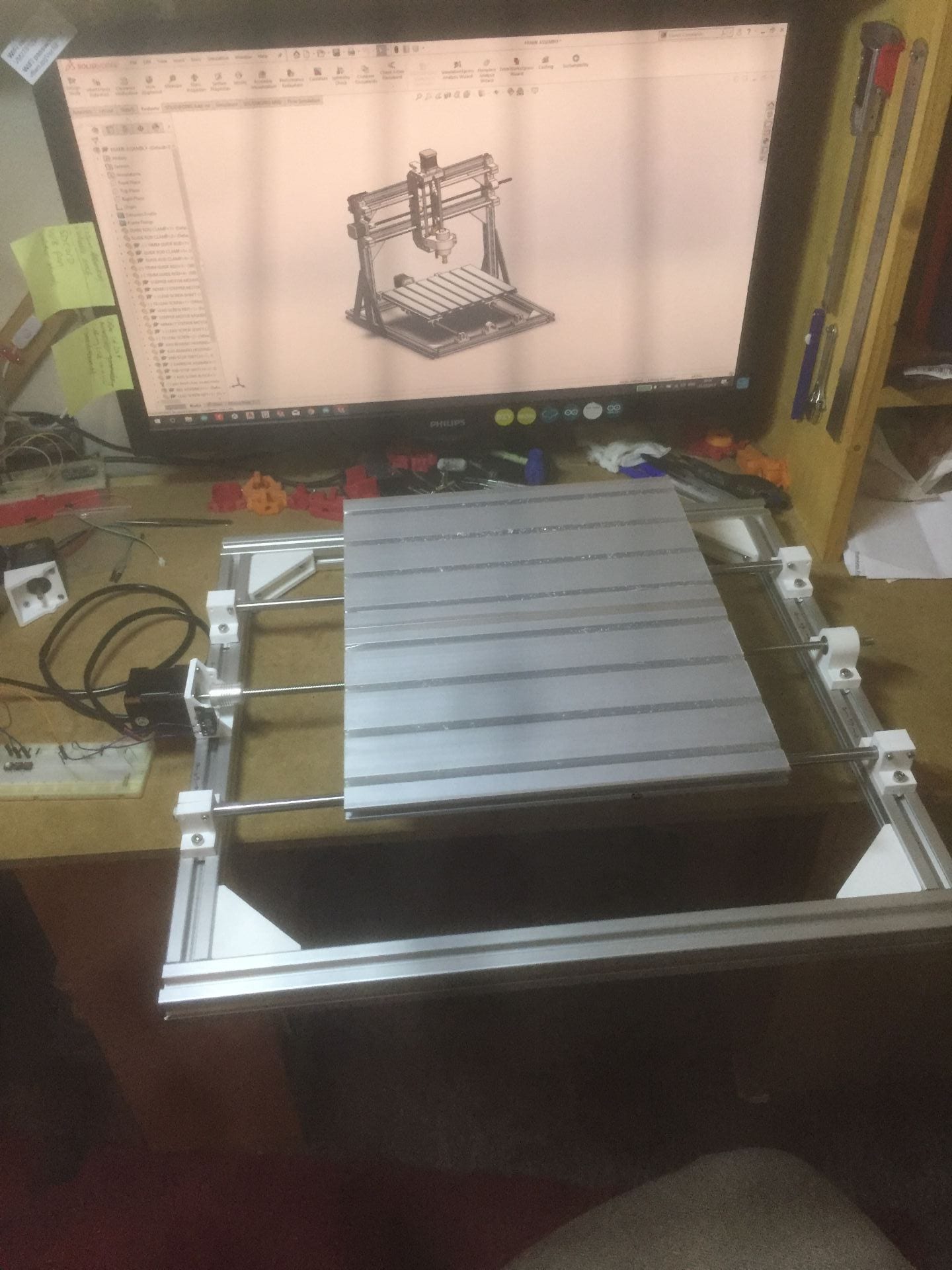
05/03/2019: Base Assembly
I have begun assembling the frame, starting with the base. This consists of 4 lengths of aluminium, 4 3D printed corner brackets, guide rods and clamps, and a stepper motor and motor mount.
I assembled the bed plate into the frame and connected the lead screw. I was able to manually move the bed with the stepper motor, and also home the axis until it hit the end stop switch.
27/02/2019: Bed Assembly
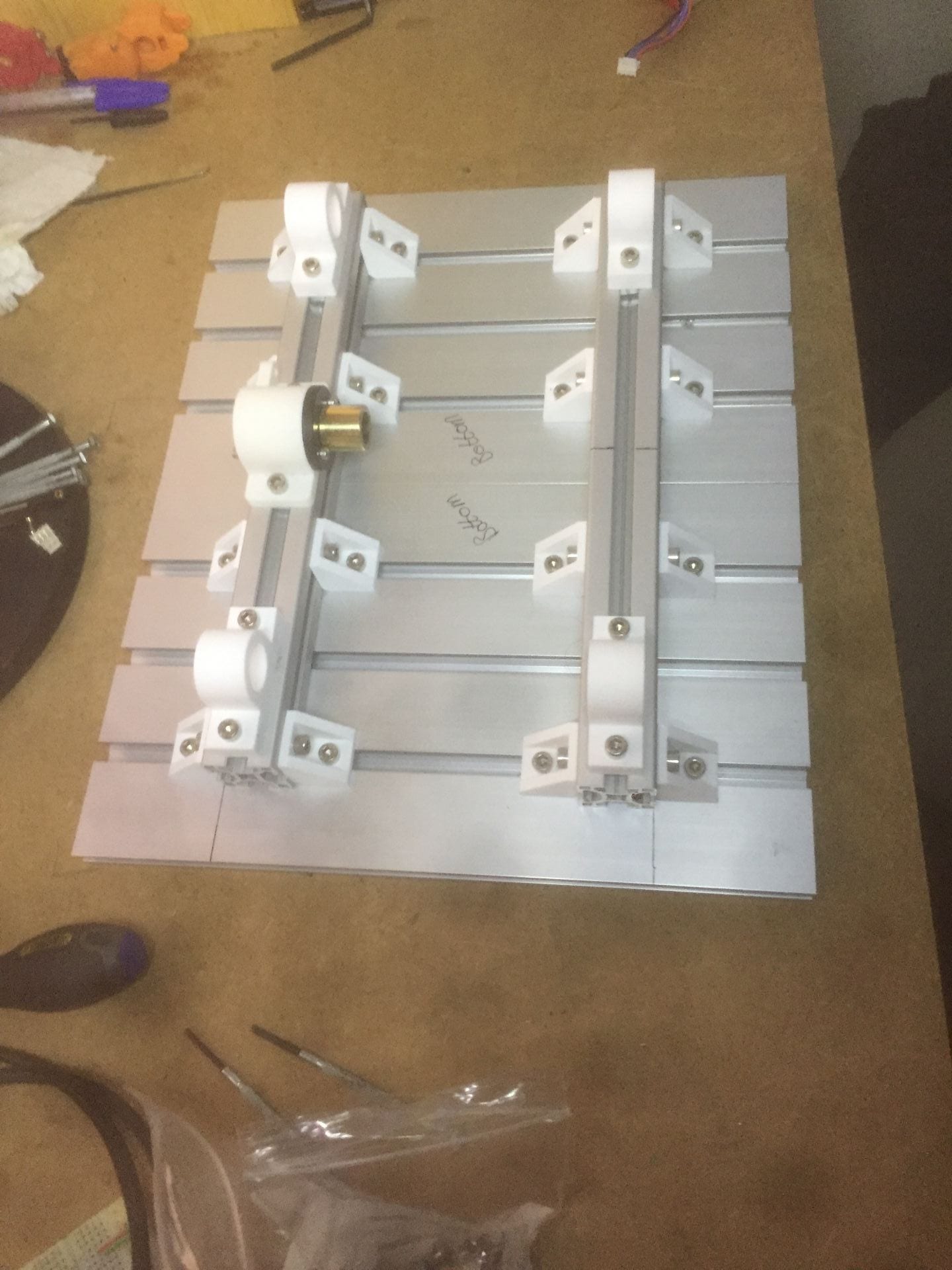
The CNC bed plate consists of two lengths of T-Slot plate to make a total size of 300 x 360mm. The two plates are held together with two lengths of 30×30 extrusion. A variety of 3D printed fixtures and bearing blocks are also part of the assembly.
The bed plate weighs 1.9Kg, im wondering how the NEMA 17 Stepper motor which moves the bed will handle it, i may need a larger motor or double up on the lead screws on the Y-axis.
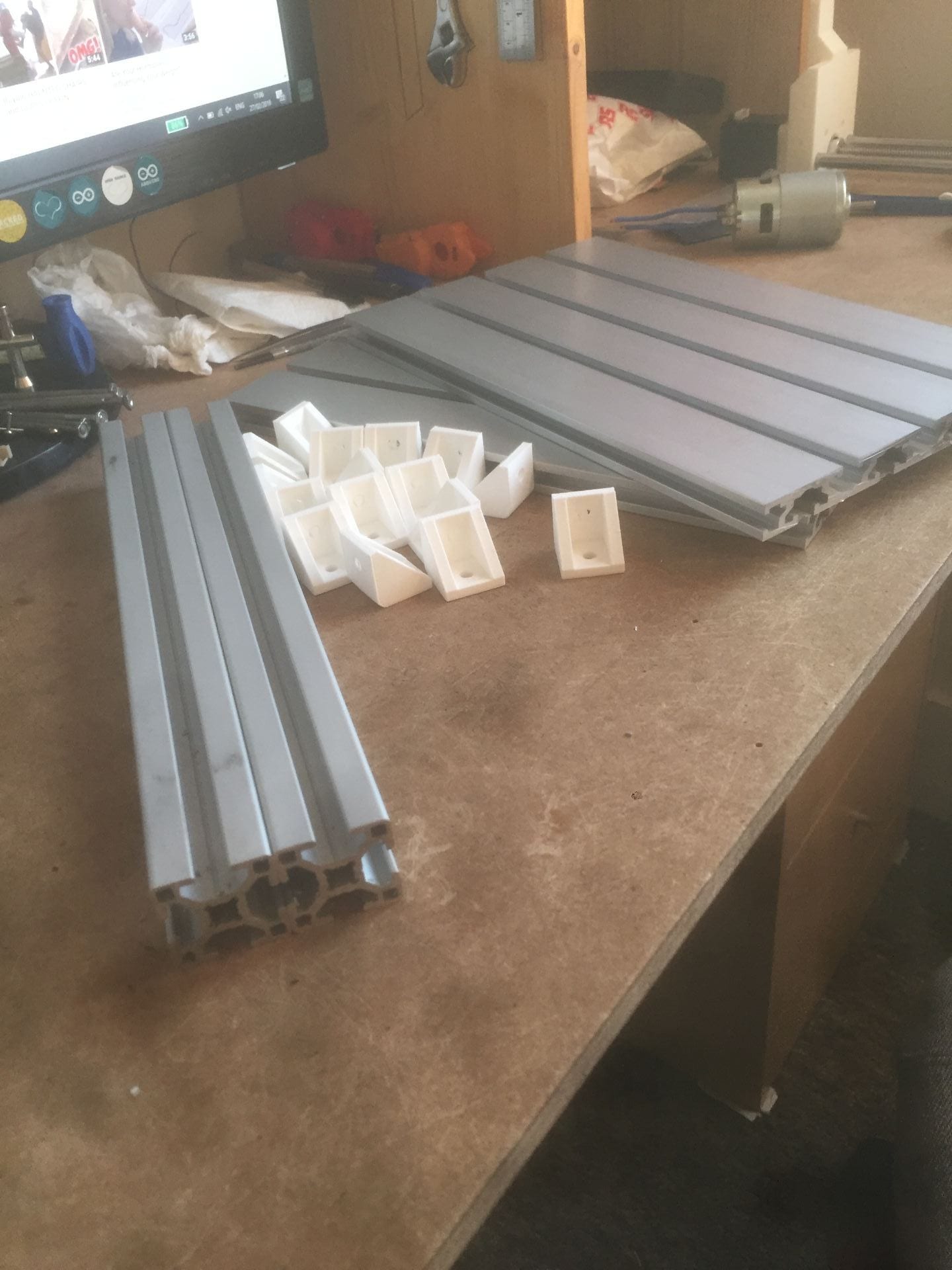


25/02/2019: Printed parts (1st batch)
The first batch of 3D printed parts are completed. This includes bearing housings, motor mounts, and test pieces for a cable drag chain.

21/02/19: 3D printing
Parts which need 3D printing have been put in the print queue at the university. There are 14 different component to print, many of which need multiple copies of. The parts are printed in PLA with 0.4mm nozzle size on an N2 Plus 3D printer.
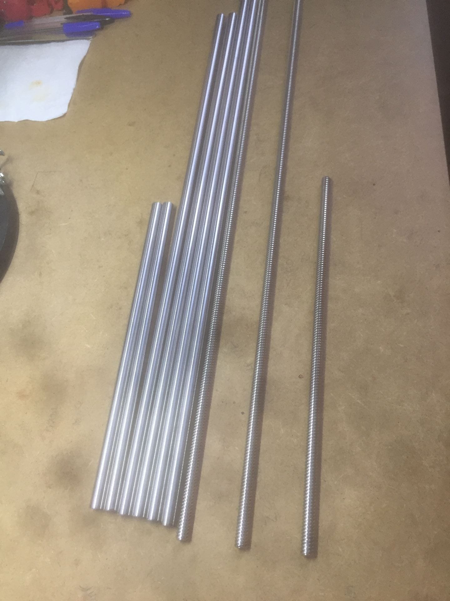
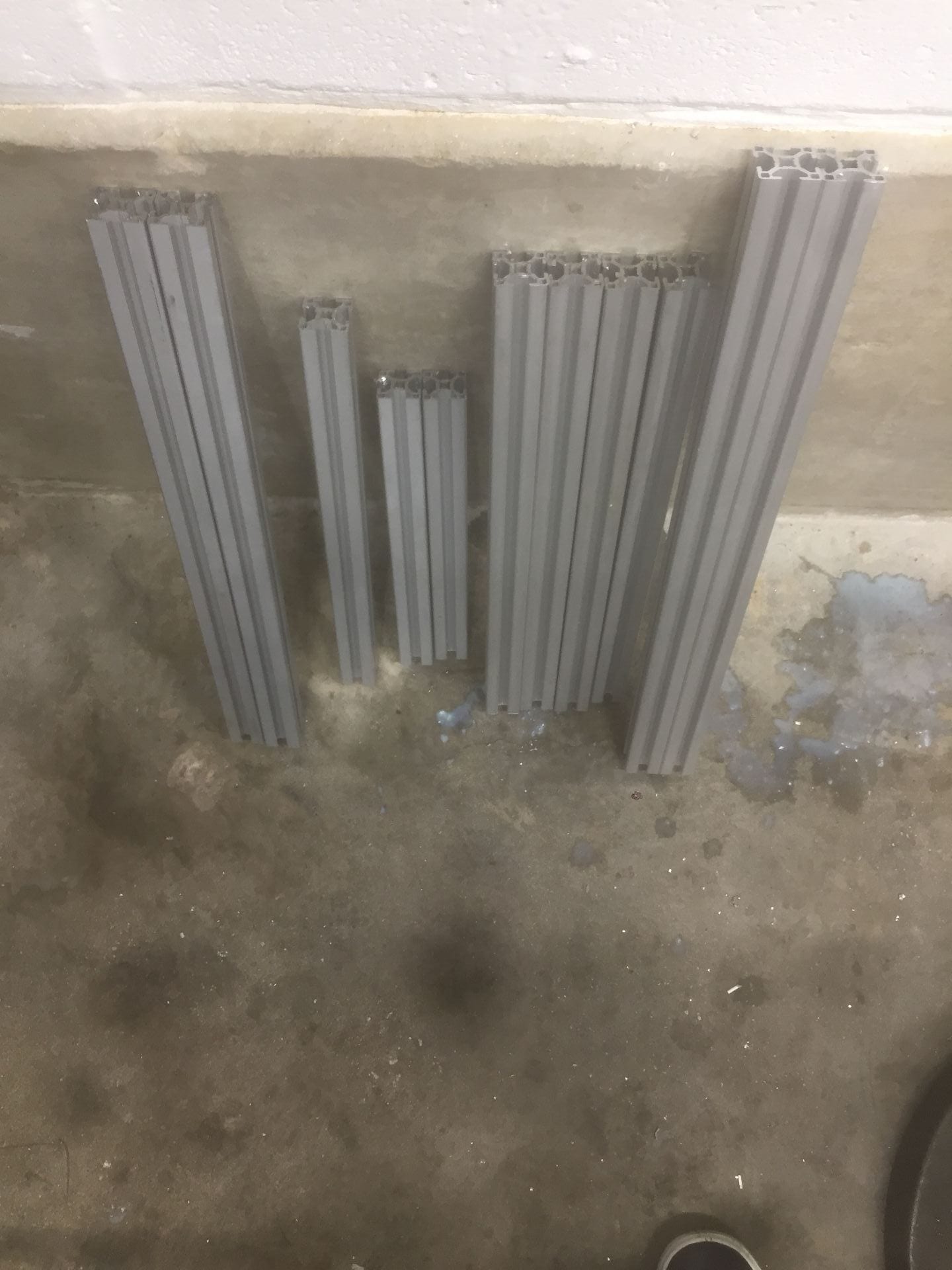
19/02/2019: Cutting material
The 30×30 aluminium extrusion has arrived for constructing the frame. It arrived in 2 and 3 meter lengths which I cut down to the required dimension with a band saw.

The guide rods came in 1 meter lengths which had to be cut down, since the rods are hardened steel, they could not be cut using the band saw. Instead a grinding wheel was used to cut through the rod, then the end was tidied up on the lathe.