Introduction
Building the surfboard got me interested in using composites. I’ve done a bit of experimentation with 3D printing and composites before and I wanted to see how far I could push the limits of this technology available to me.
I had some carbon fibre left over from another project so I decided to do some experiments with it. Carbon fibre is a woven fabric thats used to reinforce epoxy resin. You lay the carbon fibre into a mould so it goes the shape you need, then mix the epoxy resin and pour it over the top. The resin soaks in between all the fibres of carbon. When it cures, the resin sticks the fibres together like glue. 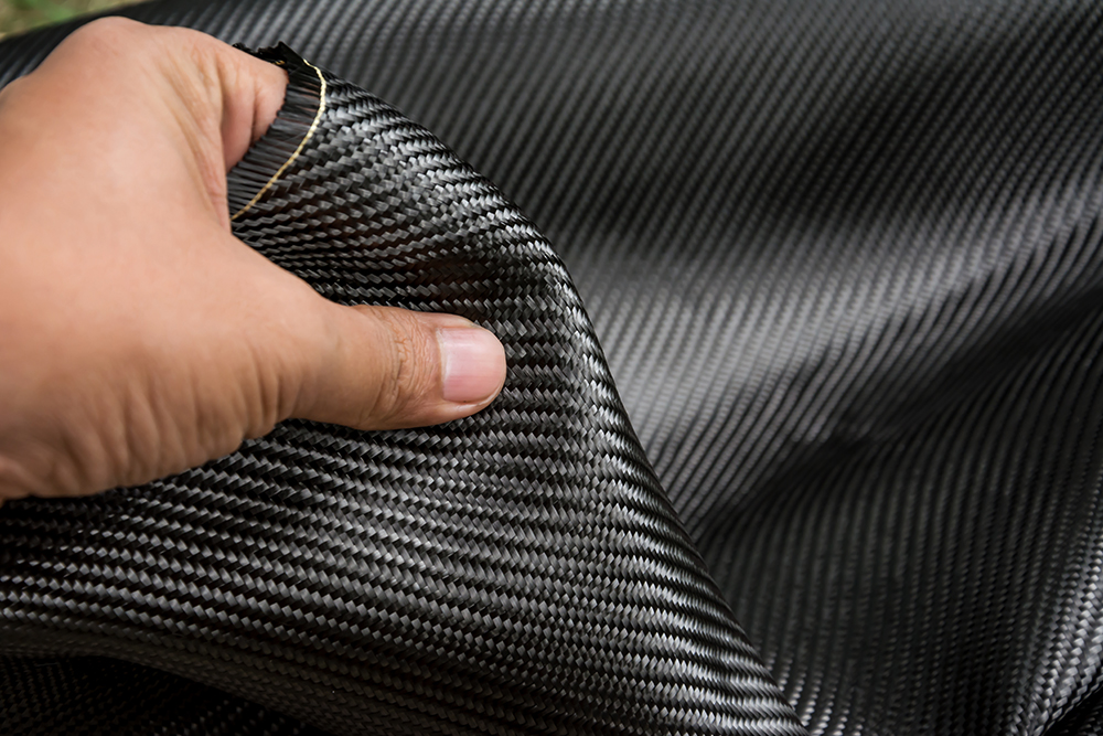
Image: https://hiconsumption.com/complete-guide-to-carbon-fiber/
Through this, the resulting material combines the incredible structual properties of the carbon fibre with the rigidity of the epoxy so you end up with a composite material that you can drape over pretty much any shape you want and will be very light and strong once it cures.
There are two main methods of making carbon fibre products: Pre-preg and wet-layup. Pre-preg carbon fibre can be bought with the resin allready included in the sheet of fibres. This is then cured by baking it in a special oven called an autoclave. Wet-layup is the standard dry carbon fibre combined with seperately mixed epoxy resin just before its put into the mould.

Making a product from prepreg carbon: https://www.youtube.com/watch?v=k4GdAuNji5g
I will be using the second method for a number of reasons: Its the material I have, I have no oven capable of curing larger products, Pre-preg materials are sensitive to temperature so need to be kept in the freezer. The benefit of Pre-preg is that its guaranteed that you get the correct ratio of carbon to epoxy (meaning stronger and lighter products) and its also easier and less messy to work with.
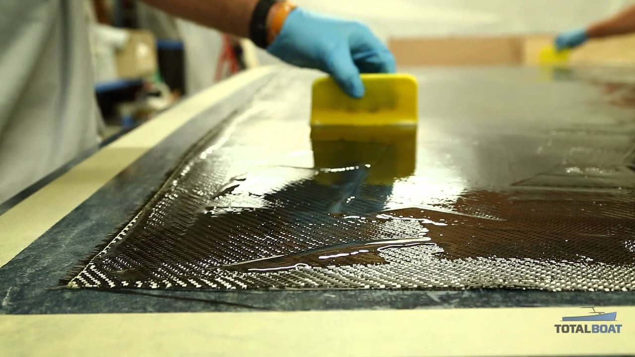
Wet Layup Image: http://www.totalboat.com/wet-layup-2/
Limitations
- Resin mixing, laminate resin contents, and laminate quality are very dependent on the skills of laminators. Low resin content laminates cannot usually be achieved without the incorporation of excessive quantities of voids.
- Health and safety considerations of resins. The lower molecular weights of hand lay-up resins generally means that they have the potential to be more harmful than higher molecular weight products. The lower viscosity of the resins also means that they have an increased tendency to penetrate clothing etc.
- Limiting airborne styrene concentrations to legislated levels from polyesters and vinylesters is becoming increasingly hard without expensive extraction systems.
- Resins need to be low in viscosity to be workable by hand. This generally compromises their mechanical/thermal properties due to the need for high diluent/styrene levels.
https://netcomposites.com/guide/manufacturing/wet-hand-lay-up/
Applications
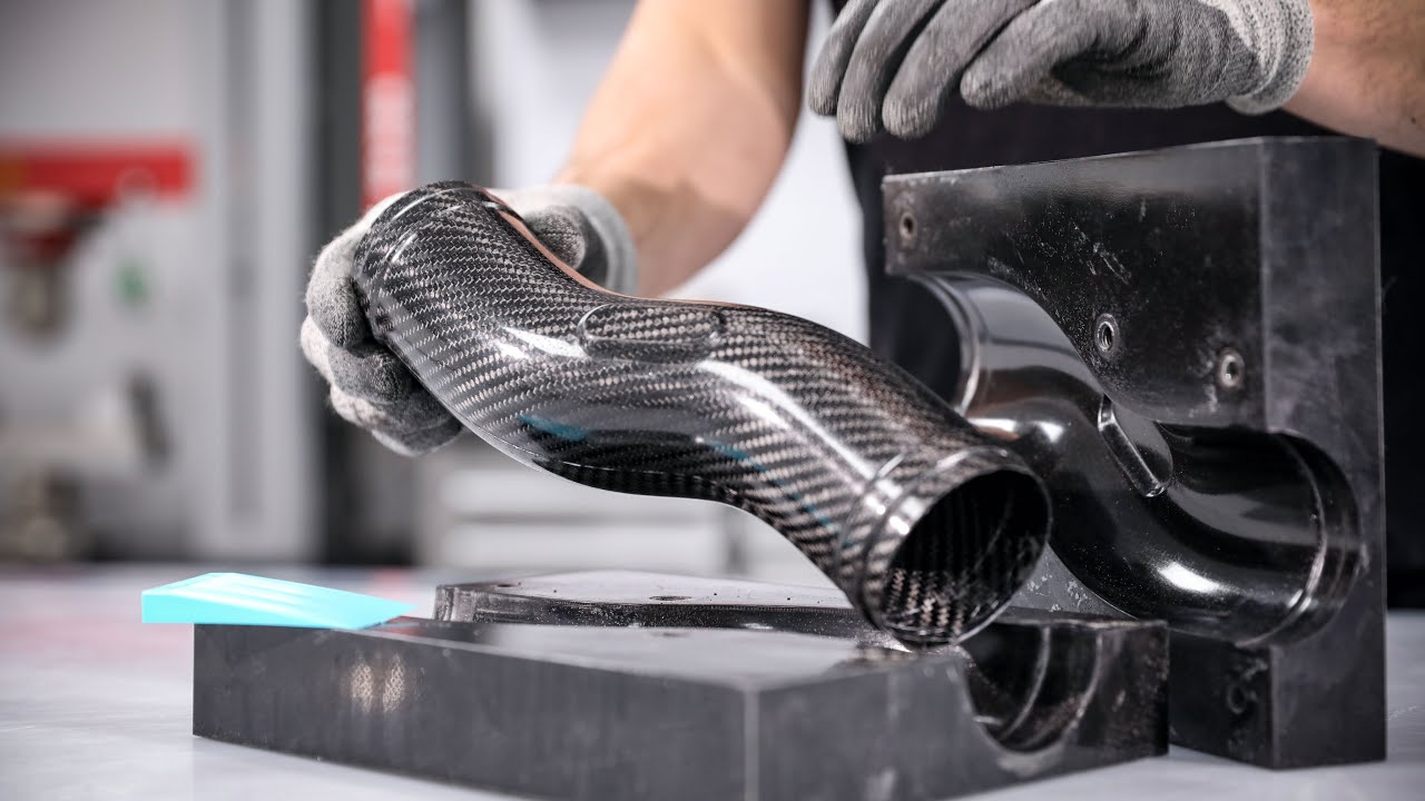
Image: https://hackaday.com/2020/07/18/techniques-for-making-complex-carbon-fibre-tube-parts/
Most of the time, very high performance parts only ever use prepreg carbon fibre becasue of its improved strength to weight ratio and how much easier it makes it to follow complex geometry. This means that wet fibre layup is generally used for less complex shapes or shapes that are too big to fit into an autoclave oven.
Safety Concerns
As touched on earlier, Resins can be dangerous to work with in a number of ways: the fumes emitted from epoxy resin, while not as dangerous as those from vinylesters and polyesters, can cause irritation of the mouth, nose, throat and lungs. This means its important to reduce the risk of inhaling them as much as possible: I have set up my working area outside, where there’s good ventilation, and wear a mask when mixing and working with resins. I also always use nitrile gloves so the epoxy doesn’t get on my hands and skin.
For more Information I read the article below with some good tips for staying safe with resin.
Image: https://www.resinobsession.com/resin-resin-resin/epoxy-resin-safety-precautions/
Sustainability
I do also recognise that because composites like this are not recyclable, there is a negative association with my experimentation process and the waste of my process is something that I aim to manage. As part of this, in the past I have kept all of the offcuts of cured carbon fibre and chopped them up to use as chopped strain carbon fibre. This is another way of using carbon fibre where small pieces are used suspended in resin to cast into moulds and it allows me to reuse my offcuts and so reduce my negative impact on the environment.
Planning

I Brainstormed some areas that I wanted to try and improve my capabilities in. From these areas, I decided on 3 ways in which I wanted to test the technology: 1. For detail (with the teeth moulds), 2. For different methods of layup (with the cube moulds) and 3. for different ways of applying the epoxy resin (With the hemi-sphere ones).
Testing
For all of my tests I wore a lab coat, mask and nitrile gloves to protect myself from the risks of epoxy and carbon fibre. Whenever I used resin, the proportions of the two part resin was mixed according to the ratio provided on the packaging. This was always done by weight on a set of kitchen scales wrapped in clingfilm to protect them. I had to use clingfilm to line the moulds because I found that without it, the 3D printed moulds absorbed the resin and became impossible to separate from the finished part.

EXPERIMENT 1: Detail
AIM: To Investigate how accurately, I can get carbon fibre to follow the complex shape of a mould.
METHOD: A two part mould with a series of pyramids was modelled in fusion 360. This was then taken and scaled at 50%, 100%, 150% and 200%. Carbon fibre was laid into each of these moulds and clamped between the two halves. Weight was then applied to the top of the moulds to keep them applying pressure to the carbon.
CONSIDERATIONS: I made sure to use 3 layers of carbon fibre for each of the moulds. They were cured at the same temperature and speed by keeping them all together and moving them inside to a 21 degree C room. I did not control the amount of resin that I applied or the amount of clamping force for each one.
RESULTS:

With these tests, I found that the moulds 1-3 produced very little deformation in the end product. I think this may have been partly due to the fact that there wasn’t that much clamping force applied. I would like to expand on this test by testing different amounts of clamping pressure and see how that changes the amount of detail I can get.
Model 4 did produce good deformation but the detail was lost on the ends of the points. This was partly due to the printer failing midway through the mould making meaning that the tips of mould 4 are cut off a little. This leads me to experiment with the printer to get better quality prints later on.
CONCLUSIONS: All of these tests needed more pressure to clamp the carbon fibre properly and make it fit the shape of the mould. However, the possibility for how effectively this could happen was limited by the inaccuracy of my printer and the poor quality of the moulds that it produced: i.e. missing the tips of the spikes and with layer shifts. Therefore in order to explore the possibilities of this technology further I would need to increase the clamping pressure applied to it and also dial in the accuracy of my printer much more.
EXPERIMENT 2: Method of Layup
AIM: To investigate the effect of changing the way of putting the fabric into the mould on the surface finish of the object produced and its dimensional accuracy.
METHOD: 6 identical cube moulds were 3D printed and had carbon fibre cloth placed inside them in different ways. The Moulds were then clamped with a single piece of wood similatneously to ensure they each had the same amount of force on them and then left to cure.
CONSIDERATIONS: I made sure that all the cubes had roughly the same amount of carbon fibre in them and that they each got the same amount of resin. The cubes were all cured together to ensure they were at the same temperature and cured at the same rate. They were all removed from the moulds at the same time.
RESULTS:

Left to right these models are:
90 degree laid fibres stuffed in, 90 degrees laid fibres trimmed to strips and then inserted, 45-degree fibres stuffed in, 45-degree fibres trimmed to strips, 90 degrees fibreglass trimmed to strips, 90-degree fibreglass stuffed in.
 CONCLUSIONS: The Ones with the trimmed fabric generally produced a nicer finish on the cube, they were also easier to insert and needed less trimming. The fibreglass cubes ended up with a really nice finish and the 45 degree carbon fibre worked much better than the 90 degree carbon fibre.
EXPERIMENT 3: Method of Epoxy Application
AIM: To Investigate the effect of changing the way that I applied the epoxy to the carbon fibre on the finish and strength of the object.
METHOD: 3 Identical hemisphere moulds were printed. These were then filled with 3 layers of carbon fibre and the epoxy was applied differently in each case. The moulds were then each clamped down with the tops in place.
CONSIDERATIONS: The moulds each had the same amount of weight applied in the clamping process. They were all cooled and cured at the same temperature in the same place. I tried to use the same volume of epoxy for each one by pouring resin for 1 second each time but this was not done scientifically so wasn’t necessarily equal.
RESULTS:

Right to Left: 1. Epoxy poured into the mould before hand, then carbon placed on top and pushed in. 2. Epoxy poured on top of carbon fibres whilst laid out flat and then spread to soak into the fibres before it was put into the mould. 3. Fibres put into mould and then epoxy poured in after and pushed around to coat sides.
CONCLUSIONS: With method 3, there were voids in the finished part where the epoxy hadn’t managed to soak all the way into the fibres. This made them weaker and was therefore ineffective. method 1 ended up with a pocket of resin on the top of the dome caused by that being added first which meant the carbon didn’t fully fill the space. Method 2 allowed the resin to soak through the layers fully and also meant I could check the carbon fibre visually to see if it had epoxy all over it. It also involved less epoxy going into the mould and therefore gave a stronger and lighter part.
Improving my printer.
One of the things that became clear from my testing is that the accuracy of my printer was limiting how precise I could get the carbon parts. As a result of this I will try to dial in the settings of my printer to get it as accurate as possible so that I can make better moulds.

The process of getting an design in your head to a physical object via 3D printing has 3 stages:
- Design: in a CAD software such as Fusion 360 (This is where you design the shape of the object. It is exported as a .STL file.)
- Slicing: in a Slicer such as Cura (This is where you set the way that the printer will print the object and adjust settings like the speed, accuracy and temperature of the print. )
- Printing: the slicer software outputs a .gcode file which is a set of instructions to the printer about what to do. (Most printers also allow you to adjust basic settings like temperature and speed while they’re printing)

My printer has a heated bed which means the area that is printed on heats up to get the plastic to stick to it. The nozzle heats up and has filament (a roll of plastic) pushed through it so it melts onto the bed. the nozzle is then moved about by the stepper motor on the frame ad the bed moves too so that you have 3 axis of movement. I can control the speed, temperature and other settings of all this within the slicer.
During the testing process, I found that the lack of detail that I was able to get the printer to produce was a huge issue. I decided to explore how to get the best detail out of my printer possible.

Especially with the wedge tests shown below, I found the the printer wasn’t printing the tips of the peaks of the mould. This meant that a lot of detail was lost on the finished carbon part. The moulds that I printed also all had under extrusion, layer shifts and odd wobbles that significantly reduced the accuracy of the prints that I was getting.

Initial settings
My Initial settings were the stock draft print settings from Cura: This was 210 degrees at the extruder, 60 degrees for the bed and 60 mm/s speed. I also had supports on (I had never tried without supports but assumed that my models would collapse if I did). I was mostly focussed on cutting down the print time as much as possible.

Trouble shooting
I watched some tutorials about how to trouble shoot your 3d printer as well as talking to Kyle (my classmate) who has a lot of experience with 3D printing. This gave me an idea of what models to print to use as tests and what to look out for to try and diagnose the issues that I was having.
Below you can see the 3D benchy (the boat) This is the standard 3D printer torture test and printing a few of these gave me a good idea of how well the settings I had changed were performing. To start off with I was trying to get my printer to print really quickly still with 0.3mm layer height.
The first benchy I tried reducing the layer height to 0.1mm. With less material coming out of the nozzle, I found that I was also able to reduce the temperature down to around 190 degrees. (I got to this by printing several iterations)
The second benchy shows me experimenting with 220 degrees extruder, 0.85mm line width and 0.3 mm layer height. I also dropped the speed down to 50 mm/s. This printed in very little time (around 1 hour) but also caused several quality issues that weren’t acceptable on a smaller detailed model like the benchy. (I will try to dial this profile in for faster printing of large less detailed objects)
I started getting these odd blobs that I couldn’t figure out the reason for. (as seen on the cylinders) I tried a few things to solve this issue: reducing the flow to 90%, using gcode from a different slicer, dialling down the temperature but nothing helped.
Eventually I figured out that the heat block on the nozzle wasn’t tight enough and plastic was seeping out the sides of it and forming blobs on the models. I removed the hot end and ordered a new one. The mistake I made when installing the old hot end was to tighten it up when it was cold. This meant it came loose when the extruder heated up.

The blobs issue had caused me to get quite frustrated with the whole process and on Kyles recommendation I changed slicer to PrusaSlic3r. At this point I also changed my default layer height to 0.1 mm instead of 0.3 mm. After doing a few test prints, I decided that the increased time cost was worth it for the dramatic increase in quality.
I starting having some issues with under extrusion (as seen with the first half of a benchy below). Usually the fix for under extrusion would be to dial the temperature up (and then flow rate too if needed) but I tried that and neither option worked. The nozzle would spit occasionally and then extrude a bit of plastic but then stop again.
After watching a couple of tutorial videos and chatting to Kyle again, I discovered that the issue was most likely A blockage in the nozzle. I used a set of 0.4 mm nozzle needles that I bought in a kit to solve the issue and unblock it.
During the process of unblocking the nozzle, I tried a few different nozzle diameters (the standard is 0.4mm): 0.8mm & 0.5mm but in the end went back to the 0.4mm one which seemed a good middle ground between fine detail and large volume of plastic able to be extruded.

I changed to a new silk blue PLA roll of filament and took some time to properly dial in the temperatures that it printed at best. You can see on the cube gears above, there is still some stringing from printing too hot. I dialled it right back to 185 degrees for the first layer and 180 for the rest of the printing and this gave better results.
I struggled with bed adhesion after this change. With the new filament, and the bed at 60 degrees, the parts got so stuck to the bed that even after it had cooled to room temperature, they required a pair of pliers to get off and I actually damaged my bed doing this.
I had a play around with bed temperatures and started off by dropping them to 55. This was actually too low and you can see the first thread that I tried failed because it came unstuck from the bed. For the next thread test I brought it back up to 57 but this wasn’t quite right because the part started lifting. I did the last test with the bed on 58 and this seemed to be the perfect balance.
Having got the temperature and accuracy settings much better dialled in, I was able to accurately print threads that I have never been able to print properly before. Below is a final benchy to show the improvement in settings quality.

Improved Settings


Link to Config Files: https://drive.google.com/file/d/1nRf_77srLG-sZJmXgIpm2QElaMpIf7jg/view?usp=sharing
The main changes are I’m now printing with 0.1mm instead of 0.3mm, my temperature has reduced from 210 to 180 degrees, speed has gone down from 60 to 50 mm/s. I replaced the hot end and the nozzles. I also got a needle kit to help unblock the nozzle in the future.
These changes mean my printer is now running much more accurately and can be used to make moulds with more detail.