BBC Micro:bit

The BBC Micro:bit is a pocket-sized programmable ‘bare-board’ micro controller that can be used to teach children and apply coding within physical computing. With its range of physical features included, presented as an ‘open development board’, the Micro:bit is a versatile device that allows the user to make a variety of coded creations. (Click here to find out more).
Anatomy of a Micro:bit
Below is an outline of some of the different parts of a BBC Micro:bit and their functions. Introducing children to the anatomy of the Micro:bit supports understanding of what each part does and how it works so that children are aware what the Micro:bit is capable of. Having this understanding supports pupils with the Micro:bit when using it to code within a variety of activities and tasks. More information can be found on the BBC Micro:bit’s website.

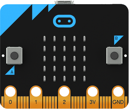
Front of the Micro:bit
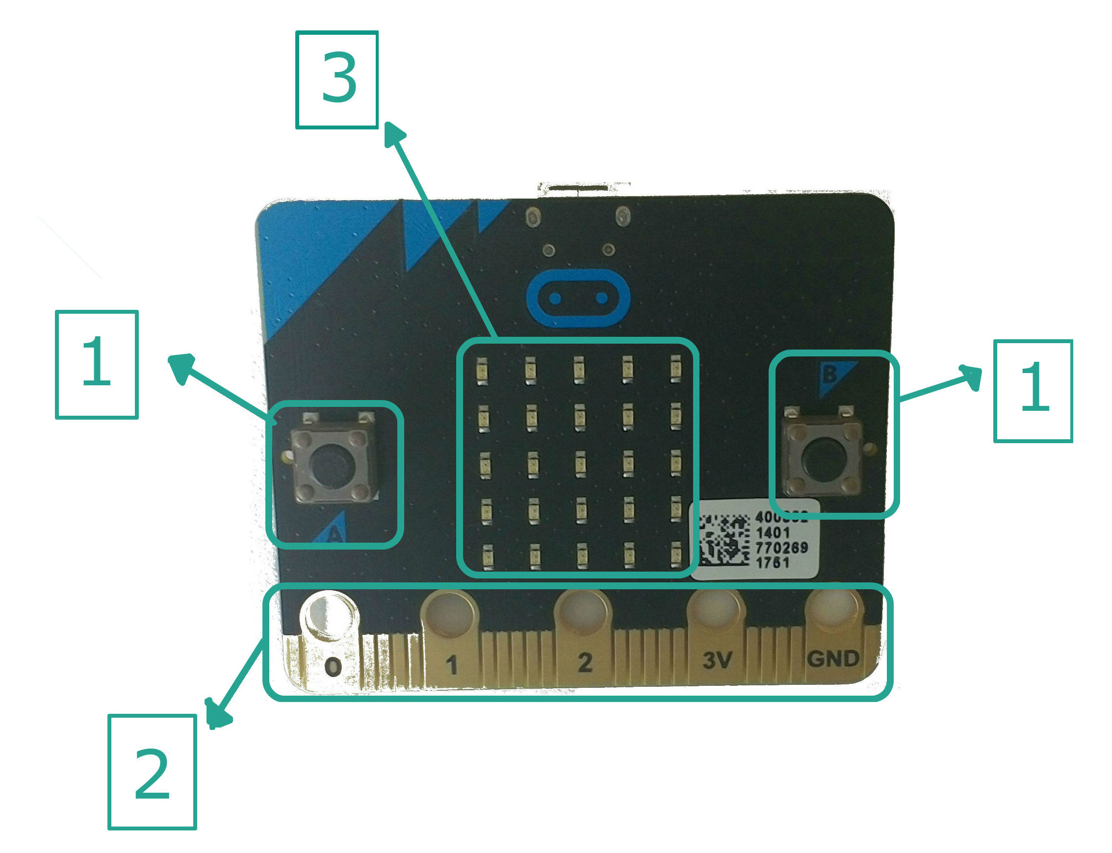
1. A/B Buttons
Two separate, built in push buttons (A and B) found on the front of the Micro:bit. These can be programmed to trigger events on the device and be used to become an input device, which can be used for interactive projects.
2. Input/Output Connectors
The golden, external connectors, or ‘pins’, are found at the bottom of the Micro:bit.
- The versatile pins, 0, 1 and 2, can be used to connect additional input and output devices such as lights, sensors, etc.
- The 3V pin is a power supply ring, where external devices can be attached to supply to or use power from the Micro:bit.
- The final loop is the ground ring (GND), is used to ground the device is the 3V pin is being used so it does not short the circuit.
3. LED Display
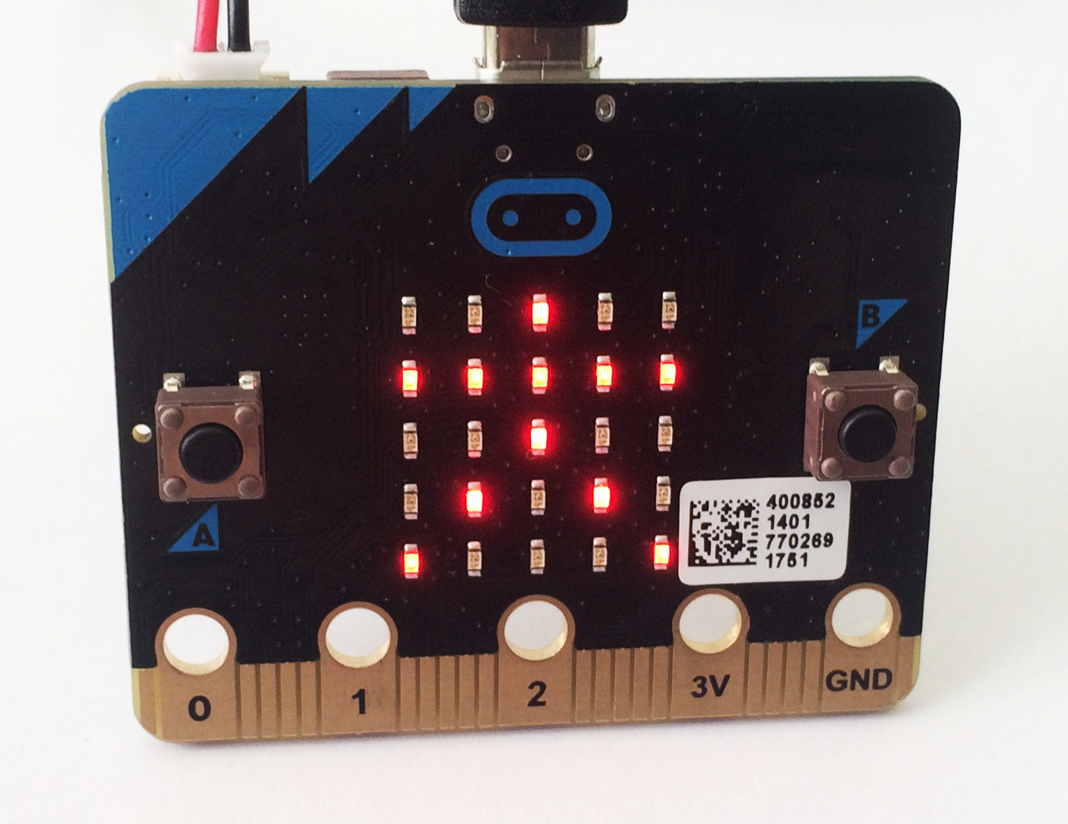
The 25 red LEDs (Light Emitting Diodes) found on the front of the Micro:bit in a 5×5 square array, can be programmed to display animation, images, symbols or text. Each individual LED is programmable to be on/off at any given time.
Back of the Micro:bit

4. Accelerometer
The accelerometer senses and measures changes in direction or movement of the Micro:bit itself along three axes:
- X – tilting from left to right.
- Y – tilting forwards and backwards.
- Z – moving up and down.
5. Compass
The magnetometer helps the Micro:bit to detect and measure any changes in movement and direction through sensing magnetic fields, just like any other compass.
6. CPU
The CPU (Central Processing Unit) is commonly known as the ‘brains’ of a computer. The CPU acts as a memory store for functional sequences and instructions for input/output devices into the Micro:bit and executes this stored data when activated.
7. Bluetooth Antenna

The antenna allows the Micro:bit to communicate wirelessly via Bluetooth to other devices with BLE (Bluetooth Low Energy) or between other Micro:bits. An example of a device that can be used is a BLED 112 Smart Dongle which allows the Micro:bit to link wirelessly to a computer.
8. Micro USB Connector

The micro USB Connector found on the back of the Micro:bit allows it to be connected to a computer via a USB port. This enables coding to be edited and transferred onto the Micro:bit and receive power from the computer, allowing it to function without being connected to the battery pack.
9. Reset Button
When this button on the back button is pressed, any code that has been downloaded on the Micro:bit will be reset so coding/programme will start from the beginning.
10. Battery Connector

When the battery pack is plugged into the battery port on the back of the device, it allows coding on the Micro:bit to be used away from the computer, without being plugged in via the Micro USB Connector. This supports Micro:bit’s wireless, Bluetooth functioning to benefitted and making projects portable, eg: through a USB smart dongle.
