Alex Judd 05 – Bridge Loads

Introduction

The important element that needs to be considered in bridge construction is the overall loads that are dissipated by the piles that the spans sit upon. This is important because an uneven or disproportionate load could cause the whole structure to fail. As this is a concept, no detail into structural calculations has been considered however there are some initial methods of predicting how the structure will act under certain loads.

Likely Concerns and Solutions

problems-with-loads

The above image shows where the likely problems associated with loads, this includes:

  • Wind
  • Vibrations
  • Overweighting and Live loads

In order to dissipate these problems, the following solutions have been proposed:

Windsolutions-with-loads

Wind is very prominent in Brighton especially being in the path of the trade winds. In order to stop the structure resisting against this, it has been opted that the design of the bridge lets the wind pass through it. This negates the impact wind and diffuses it through the structure as opposed to around.

Vibrations

Vibrations from traffic will be very prominent so in order to reduce the effect that the vibrations have on the structure. Multiple piles have been selected as opposed to the original upright two piles. This means vibrations are spread and dissipated through the structure as opposed to a fixed location. This will stop soil loosening around the foundations and also stop the build-up of structural vibration.

Overweighting and Live Loads

It is important to consider the live loads on the bridge. By having no sort of lane control on the deck, the pattern of vibrations caused by these loads could be vast and quantifiable. Therefore, by splitting the deck into different pathways, we can focus the live loads on a certain location so there can be suitable reinforcement for this.

In summary, the intention of this preliminary examination into the loads of the structure is to inform us of how we can reduce the loads occurring on the structure before a technical design submittal where the calculations and engineering of the bridge take place.

Alex Judd 04 – Site Levels – RevA

Reason for Revision A

Upon reflection in our group, we have decided that crossing from Preston Barracks to the Mithras House entrance would be too high up off the ground and would pose more problems in relation to who uses it and how it is accessed.

We have decided to go for bridge option 2 as mentioned in the first revision. This involves positioning the bridge to the most northern part of Mithras House car park and then spanning over to the proposed central square at the Preston Barracks development OR Watts car park dependent on Preston Barracks development outcome.

The levels won’t be affected per se however we will be bridging from the 30m above Ordnance datum as opposed to the original 35m, this reduces wind loads but also mean that the ramps and accessibility aspects which were a concern in the first instance are drastically reduced.

Alex Judd 03 – Cased Based Precedence – Bike Ramps

Bike Ramps

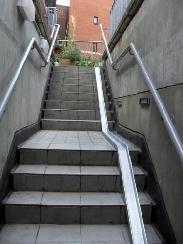
In a lot of train stations where there are bridges over the railway there is a problem that bikes have when it comes to crossing platforms. Elevators are available for use in many cases but these may be too small to fit in multiple bikes and people. What is often used instead is a ramp fixed to the stairs that allows the cyclist to push their bike up the ramp why they too go up the stairs. This also applies going down the stairs.

wheeling_2

This can certainly benefit the end user as the strain of carrying a bike up the stairs or trying to fit into a tight space is reduced and in some cases negated. It’s a very simple and efficient method to help bikes out significantly. However, consideration into the type of ramp needs to be addressed.

large_sam_1242

Concrete formed bike ramps are safe and secure however cannot be moved at a later date. Metallic ramps are more susceptible to damage and in some cases can be harder than the concrete stairs as the wheels can rub against the side. The benefit of using a metallic ramp is that these can be easily removed, replaced and fixed to any type of stair.

Our project could include a metallic ramp but with a much larger width. Perhaps it would be wise to combine both the concrete and metallic ramp so there is a ramp present but with the option of a channel for your bike to sit in incase the user is struggling to push these up.

wheeling-ramps05

The above image also shows how it is fixed to the stairs. This is by fastening the metallic ramp to the highest concrete stair and stair base with concrete anchors.

Reference: http://cycle-works.com/product/wheeling-ramps/

Alex Judd 02 – Cased Based Precedence – SEW V Bridge

V Bridge

The ‘V Bridge’ is a proposed bridge at Nine Elms, London by architectural firm Studio Egret West. It spans over 150m with two piers sunk into the bed of the river that it passes over. The bridge uses a very simple process of splitting the cycle path and pedestrian path across the breadth of the bridge deck.

V Bridge

A main concern raised in our group was the fact that cycle paths and pedestrian walk ways on a bridge could be hazardous in the instance that they could collide at a point. This proposal handles this very well and I hope to incorporate this into our design. It also has various seating arrangements and foliage on the bridge itself which for the instance of this project may not be required but may be worth considering.

V Bridge

The disadvantage with this bridge design is that it is very different scenario to ours; In the instance that this bridge were to cross an A road, I doubt that it would use this sort of structural system in the intended design.

In brief, the element we wish to source from this cased based precedence is how it deals with the end user. Even if the design does not split, there needs to be a control element put in place.

Reference: http://egretwest.com/projects/v-bridge

Alex Judd 01- Site Levels

Introduction

Site levels are important for a competent bridge design, in particular when it is crossing a busy highway and needs to be made accessible to all parties. On 07.11.2016 the UoB and Haselwick students went on a site visit to the A270 and Mithras House Building on the Mouslecoomb campus. My intention of this visit was to get a better ‘feel’ for the site, especially for such factors like the line and level. In order to document this I took some photographs of the location.

img_0939Mithras House

Bridge Option 1

We agreed in our group that a crossing spanning the entrance of Mithras House and the proposed Preston Barracks development would be possible. However the change at levels at this location is significant. Therefore, I went out to find these through study of existing topography. Using Digimaps, I downloaded a site plan and overlaid this onto a topography expressed in 5m contours. By overlaying both these levels and the site plan, I could take some levels from the site.

Overlay of Levels

I struggled to establish levels of the lower stairs going up to Mithras House through the desktop study, and in order to establish these levels I used a reasonable assumption from the photographs we took of the site. I then sketched these levels.

Levels Sketch

Bridge Option 2

An alternative to this crossing point would be at a lower level more towards the corner of Preston Barracks as with the planning application made for the Preston Barracks development. This would still use the same levels as expressed above but instead of crossing at high level, these would cross at the lower platform.


Mwaka Musuumba Humber -Day 1(ideas, briefing and getting a flow of thing)

Bridges, cyclists and footpaths.

Those were the main points I got from the briefing that was delivered this morning.

A group site inspection was carried out in order for everyone to have a better understanding of what surrounds we were working with. On this visit I took plenty pictures, that way when it came to designing we wouldn’t have to venture out into the cold again.

Once back in the warmth, sitting in our group we decided to start sketching down some ideas.

Something Noel said to us while on site struck out to me and boom I had it.
I was inspired by a spider, with it’s 8 legs, being the difference access points for the cyclists and the pedestrians.

After making a rough sketch and pitching the idea to the rest of the group they were sold on it.

And like that the day was over, our leader set us homework on doing more research on types of bridge supports, materials etc. Just to further our understanding.

Bridge in Krakow (Poland)

b1 Over half term we visited Krakow, in Poland, and walked across this bridge. The first image is the view across the bridge. The second image is a view of the bridge span. I’ve blurred out my family’s faces; apart from my youngest daughter who is always very keen to be on camera.

b2

Menai Bridge

20161107-135404.jpg

The Menai bridge is a suspension bridge to carry road traffic between the island of Anglesey and the mainland of wales.

Designer ~ Thomas Telford
Location ~ Northwales
Materials ~ Wrought iron and stone
Contruction time ~ 7 years, 1819-1826

Dimensions

Total Length ~ 417 Meters
Width ~ 12 Meters
Height ~ 30 Meters