This module has two projects. I was in two different groups, the first projects was to produce a pinup and poster of a submarine camera. My area of work within this group was background research, project planning and I also helped out with the justification of subsystems.
The second project was to produce a battle robot for robot wars, my contribution was producing the Gantt chart, concepts, CAD model and I also produced an engineering drawing for the weapon of the battle robot.
Contents
SUBCAM PROJECT
The first task of this project was to produce a pinup. I was assigned to producing the project plan, as well as doing some background research on the subcam. There were other people assigned to the background research so my contribution focused on the project plan. Here is some links which I found to help with the background research
Subcam Background Research
Stabilization of a camera for submarine image visualization http://rainbow-doc.irisa.fr/pdf/2001_cviu_cretual.pdf
Hydrodynamic design of a submarine https://apps.dtic.mil/sti/pdfs/ADA428039.pdf
Depth control under wave disturbances https://ieeexplore.ieee.org/stamp/stamp.jsp?arnumber=406981&casa_token=BEYeazNbpNAAAAAA:s59FCwIXioSGaNBZNJWfaXY6uT5xqgdXROgoBW8bwxSGrqRJ8S4Mj1iK2qZBn9bE4jORWls6-HSf&tag=1
Existing designs https://www.dpreview.com/articles/1561165185/ttrobotix-introduces-ttr-sb-seawolf-submarine-for-gopro-cameras
https://wetpixel.com/articles/anglerfish-announces-deep-housing-for-panasonic-bhg1
Project Planning
For project planning I decided to produce a Gantt chart, I thought that this was the best option as this would allow for myself and the rest of the group to see who has what tasks, when deadlines are, how long each task has taken and what tasks are left.
An alternative to this would have been a checklist, this wouldn’t have worked as we had deadlines that needed to be met and a checklist doesn’t allow you to dedicate a set period of time to tasks, if we had chosen this method we would have ended up with unfinished work and work that hasn’t been started.

Poster of the Subcam
DOWNLOAD: XE521 Poster
The poster is a combination of the whole groups work and includes: Project Planning, References, Ease of Construction, CAD Models, Risk Assessment, Appropriateness of the Design and Justifications.
Justifications
For the poster I continued with the editing of the Gantt chart. I also helped a team member create the Justifications. For this I focused on providing some mathematical equations on uniform pressure for both unstiffened and ring-stiffened thin-walled circular cylinders. These equations are relevant as our subcam will be submerging and we need to know the pressure that the subcam can withstand. If we didn’t take this into consideration our design could ultimately fail.

This was used so that we could justify whether or not we should have a supported interior to the subcam.
ROBOT WARS PROJECT
Gantt Chart
In this project our goal was to build a battle robot to fight robots produced by the other groups.
The groups first task was to produce a pinup proposing our robot concepts. For this activity I produced a project Gantt chart. Here I had to take into account what everyone was doing and I had to ensure that the project would be completed before the deadlines.
I decided to make this Gantt chart similar to my own for the design engineering course as there were multiple deadlines, we had a pin-up, the making of the robot and a group report on the whole project. I felt that splitting the Gantt chart like this helped as it allowed for the group to not become confused when taking on multiple tasks and it also allowed for everyone to get a fair share of tasks.

DOWNLOAD: XE521 Group 9 Robot Wars Project Planning
Concepts and Digital Concepts
For the Pinup I also produced a couple concept drawings. The First was based of a castle tower and the second design was of a skull.

Here is the digital version of the concept:
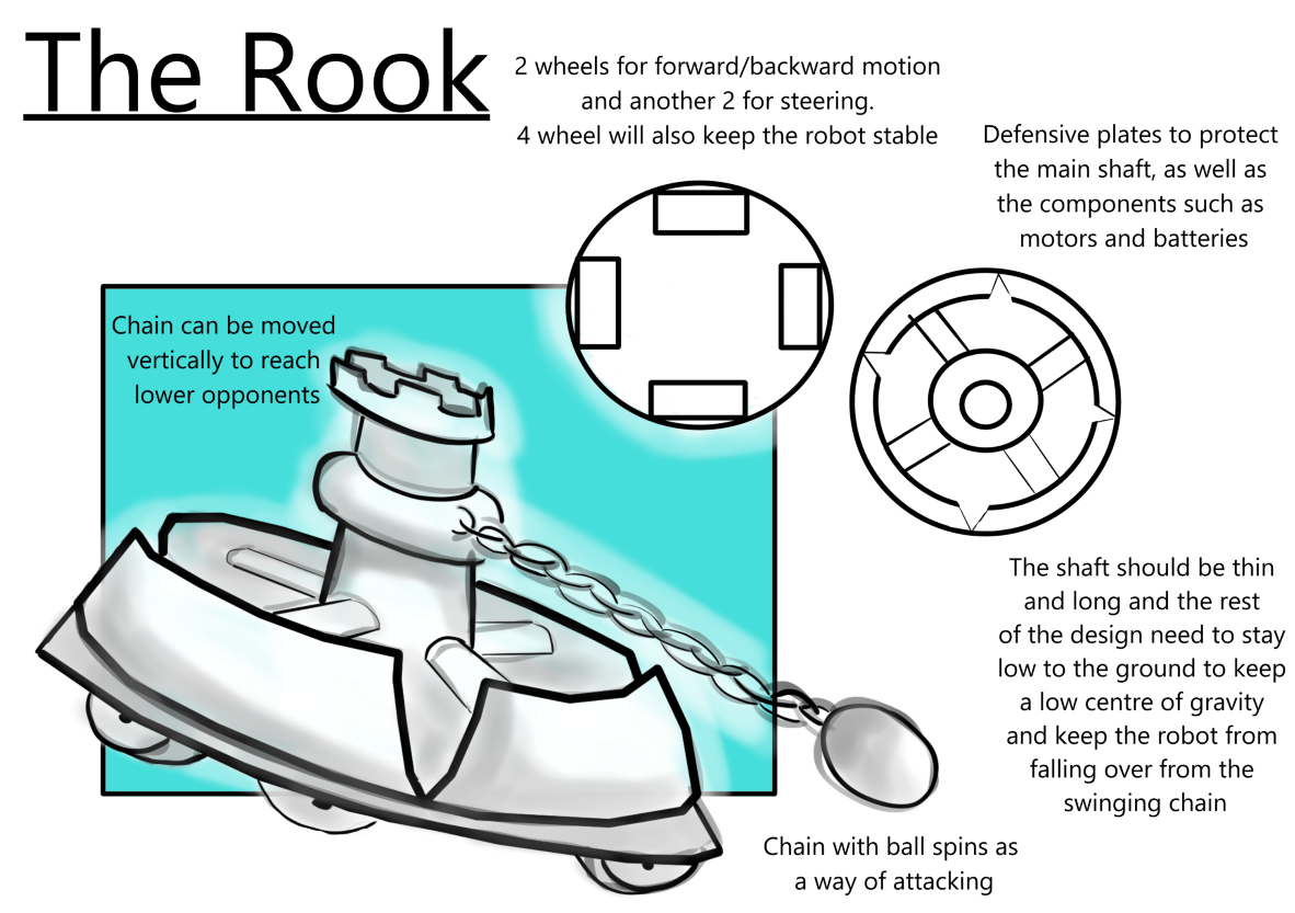
The idea behind this concept was to have a weapon which could act both offensively and defensively. I came up with a ball on a chain that would be spinning around. This way the robot could attack from all sides and keep the other robots from getting close.
A problem with this concept is that the ball would struggle with hitting low enemies, I came up with a few ways to resolve this, the first way is by having the main shaft be able to adjust the height of the swinging ball. The second resolve this is by having the part which spins at an angle so that the swinging ball swings at an angle and not horizontally.
For this design I also produced an exploded view to show how the robot would fit together and to show the main components that make this design

This is my second concept drawing for the pinup, This design is mainly aesthetic and this concept uses a case to store and protect the mechanisms of the robot.

Here is the digital version of the concept:

Digital concepts were made using Krita
CAD Modelling
After producing these concepts I used Solidworks to produce a CAD model of my first concept drawing.
This is the CAD model of the first concept, its slightly different, I felt that there was little protection on the main shaft itself so I added a second layer of plates. I also reduced the number of plates on the layer so that if this design went further there would be less cutting involved.
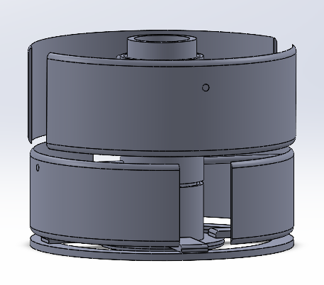

This CAD model consists of a main base, main shaft, plate holders, bottom plates and top plates. The plates will have a thread where they can be tightened to the main shaft. I have also made it so the plates height can be adjusted if needed.

I also added a weapon base and a weapon attachment part on top of the main shaft so that the swinging ball part could be added. The swinging ball will be at an angle so that it can reach the lower opponents.
Here is the ZIP file with all the components and the current assembly for DOWNLOAD: The Rook Robot Assembly
Assembly Drawing for the Rook Assembly

Engineering Drawing
After some discussing with the group, we decided to go with another concept which another member had produced. We came to a conclusion that my designs were too complex and it seemed too unreasonable to build in the amount of time that we had.
Once the concept was chosen, I was tasked with producing an engineering drawing of the weapon to be used for the robot.
Here is an image of the weapon:

I used Solidworks to produce this drawing.

Unfortunately due to the lack of time and some unforeseen issues the flipper arm wasn’t built and instead a spike was attached to the robot instead. The robot weighed 8kg.
Here is the robot and a video of it in action:

Despite the lack of time, the weapon change and all the other small issues. We managed to win the battle.