The first part of this page uses information I found on Dr Covill’s page. It contains basic knowledge required to get started with producing simple electronics.
The basics
Electrical devices are powered by electricity (e.g. lights, kettle, fridge, toaster). Electronic devices use electrons in a clever way (e.g. to control a robot or display like a TV).
Ohm’s law: Voltage (Volts) = Current (Amps) x Resistance (Ohms)
V = I x R
Note also that the power used by the circuit is also an important consideration, where Power (Watts) = Current (Amps) x Voltage (Ohms)
P = I x V
A good analogy to understand what these terms are. Voltage determines how much oomph you can get. The resistance indicates what is restricting the flow. The current is how much stuff is flowing.
Getting started:
Components
- breadboards – allow you to connect items up without solder – not very robust Here’s a good guide to using breadboards. Alternatives are:
- wires – conduct electricity (larger diameter = can take more current)
- resistors – resist flow of electricity, here’s a resistor colour chart and calculator
- potentiometers – are resistors where the user can vary the resistance
- capacitors – store energy (kind of like a battery) in an electric field. They store charge and tend to smooth out changes in current.
- inductors – probably won’t need these just yet, but an inductor stores energy in a magnetic field when electric current flows through it.
- buttons – like switches, but only make connection when pressing
- switches – allow toggling between open circuit (no flow + no activity), and closed circuit (flow + activity)
- diodes – only allow current to flow in one direction (where the arrow is pointing). Note that LEDs are Light Emitting Diodes – they are a type of diode.
- batteries – provide voltage potential – i.e. they store energy (typically are 1.2, 1.5, 3, 3.7, 9, 12.6V)
Circuits
There are 2 possible types of circuits that determine how the components are arranged:
Parallel = next door // Series = inline
Signals
Analog waves are smooth and continuous (e.g can vary anywhere between 0-1)
Digital waves are stepping, square, and discrete (e.g. are either 0-off, or 1-on).

Note that you can represent an analog signal digitally with PWM (pulse width modulation). This simply turns the signal ON and OFF in different amount to give an overall average percentage ON (voltage output).

PWM representing analog signals digitally
Input devices
Input devices allow the input information to a circuit. They can also be sensors, because typically they sense something in the environment (e.g. temperature, humidity, light) and quantify how much of it there is in some way (e.g. temperature in Degrees Celcius, humidity as a % and light as light intensity or Lux). Some examples of input devices you can use in circuits are:
- temperature: thermistor, thermocouple
- light: LDR (light dependent resistor), or photodiode (more accurate)
- distance: sonar sensor
And many others, e.g. magnetic field, acceleration, sound level, vibration, force, pressure, angle, image.
Some sensors are passive and can simply be plugged in and they change resistance with a change in property (e.g. LDR resistance changes as you change the amount of light). Other sensors are active which means they require their own circuit and power source.
Output devices
Output devices do something. These can be motors (DC, brushless DC, servo, stepper), lights, speakers, solenoids, displays. Note. output devices sometimes need special drivers to make them work, and often the require quite a lot of power to operate, a separate power source may be required.
Initial task
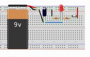
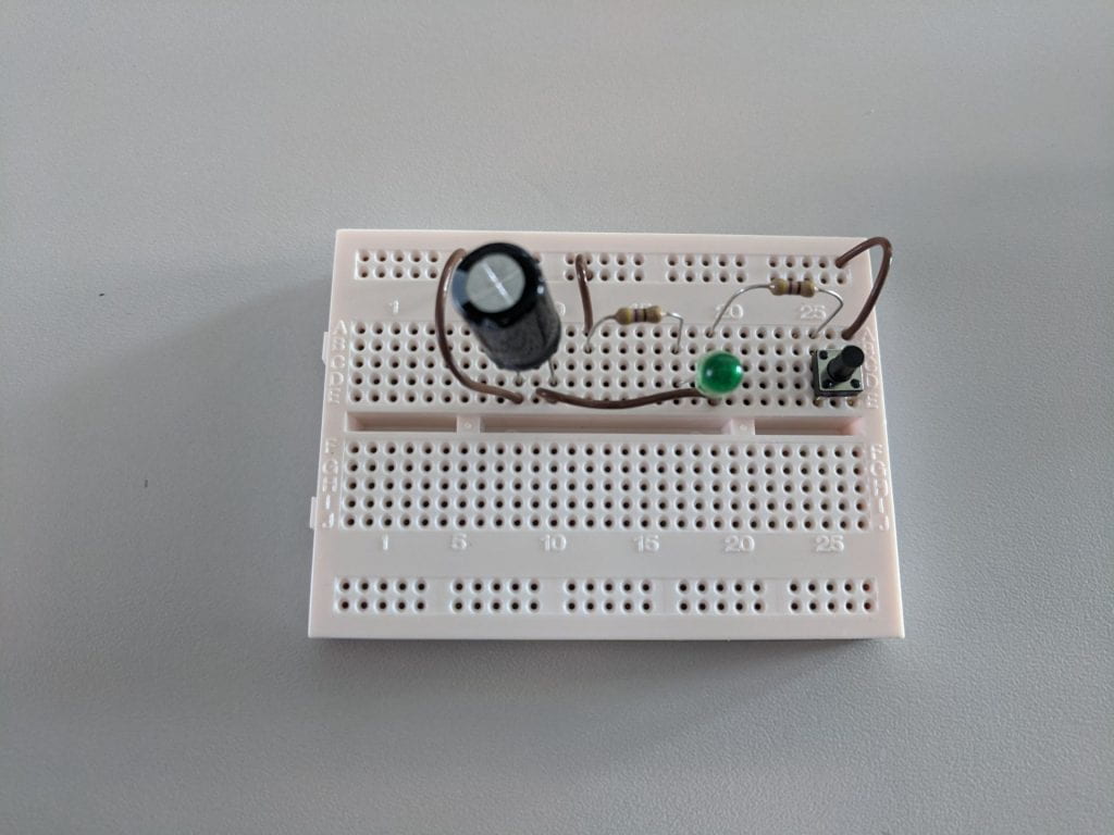
We were tasked with creating a simple circuit on a breadboard that used an input, output and a capacitor.


The circuit was powered with a 9v battery. It had a button (input) which when pressed illuminated the LED (output).

The capacitor meant that when the button was released the LED stayed illuminated for a short time.

Unfortunately this circuit didn’t work as intended – the capacitor didn’t have the same effect as it had with the previous circuit.

Second task
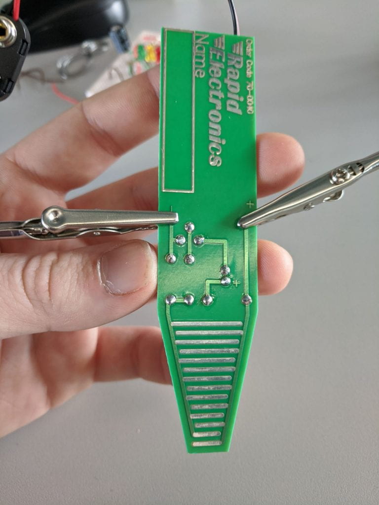
The second task was similar in that it required us to create a circuit that included an input and and output. The main difference was that rather than using a breadboard we used a pre-made PCB and soldered the components on.


This a kit produced by Rapid Education, available here. This was more an exercise in following a wiring diagram and soldering technique.
I did learn how to use a dc power supply but I’ll leave it to this video to explain how that works (it’s long but by far the best, skim through it).
The real fun happened next week.
