The aim of this week was to build on what we learned in week 4 – Electronic Production. The tasks were:
- Design a breadboard and PCB circuit in Fritzing.
- Programme a Micro:bit using an input device (e.g. button, LDR), and make it drive an output device (e.g. LED, buzzer, motor).
- Experiment with different input and output devices too.
Fritzing!
The Fritzing software is a good little package but it can’t be used to test if a circuit will work. It does link directly to manufacturing and you can purchase the PCBs directly through the software. It can be downloaded free here: www.electroschematics.com/fritzing-software-download
- Moisture Tester

This is the moisture tester that I made last week

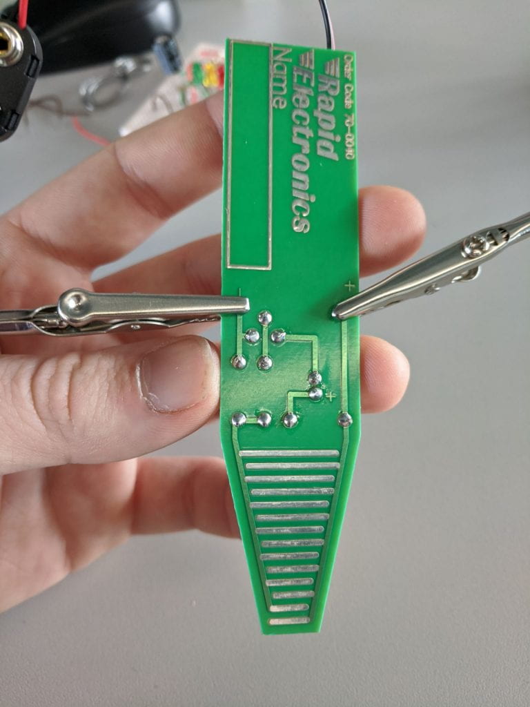
The reverse side of the moisture tester
In the Fritzing software it looks like this:

Each component can be dragged into position and the values adjusted accordingly.
Note. The way the moisture sensor works is that it basically has many open contacts that the moisture can complete the circuit across, there isn’t a component for that in Fritzing so I used a switch (S1) as a place holder. Also, for this circuit the power supply is actually 9v!!
- Slow Dimming LEDs
In the Fritzing software you can design circuits as if you’re using a breadboard. I made this 3 switch, 3 LED, 3 capacitor circuit where the LEDs slowly dimmed after being switched on.

It was quite a messy build on the breadboard

The colour of the wires match the LEDs they relate to
Micro:bit
There is more info and details about Micro:bits here.
We made a circuit that uses a light dependant resistor (LDR) as an input, the Micro:bit displays the reading.


Very messy soldering/connections but it works
This is the remarkably simple code to make it work

Essentially, when button A is pressed display the reading from pin P0 which is where the LDR is connected – simple.
Levelling up
Another challenge was to connect an OLED displauy and get it to display a reading such as temp. As I had a 16 pin LCD screen I decided to try that instead – how hard can it be…
Tried to do this tutorial – https://maker.pro/microbit/tutorial/how-to-setup-an-lcd-screen-with-microbit
Using Python for Micro:bit – https://python.microbit.org/v/2.0
The LCD is much more complicated to wire up compared to an OLED display. It also requires a potentiometer (variable resistor) and a 5v external power (that became important later).

Fritzing diagram of how to connect an 16pin LCD display to a MicroBit

The messy result of my LCD wiring
My first attempt to follow the tutorial didn’t work, the LCD powered up but that was because it was powered by the power supply.
I found another example online and had another go – http://www.multiwingspan.co.uk/micro.php?page=lcd
It still didn’t work and this is almost certainly because it required using a Python style method of programming which I’m not confident with.
This didn’t matter as during my second attempt the power supply spiked from 5v to 25v . Everything got very hot, especially the processor on the Micro:bit and it was not longer responsive. Nothing when reset, nothing when connected via USB. Toast.
After all this I did find this simpler way to connect LCD that is specifically designed for Micro:bit – http://www.suppertime.co.uk/blogmywiki/2019/11/microbit-colour-lcd/
OLED
Back to the suggested task of using a 0.98″ 128×64 pixel OLED screen to display temperature – as suggested…
My class mate Kyle had already documented this project on his blog so I used his info and these two tutorials:
- http://www.suppertime.co.uk/blogmywiki/2019/11/microbit-oled-display/ – uses Micro:bit block coding
- https://www.littlebird.com.au/a/how-to/81/0-96-oled-screen-with-micro-bit – uses Python style coding
I aimed to recreate to process on the suppertime.co.uk post as it used Micro:bit block coding. Below is the string of code as suggested on the post:
Quick note: This code requires the approved MakeCode extension. Once you add the MakeCode extension, you connect your display using just 4 wires: GND on he display to micro:bit GND, VCC to 3v, SCL (serial clock) to 19 and SDA (serial data) to micro:bit pin 20.
After running this exact code both myself and Kyle had the same experience. The OLED worked and when prompted did display the temperature. However, we also found that it didn’t work like the tutorial suggested and there was a lot of code to display additional info and text characters that wasn’t working – as we both had the same issues we decided to work together to resolve it.
We also both had an issue with a permanent line that was being drawn across the screen at all times, covering other displays – as seen in this video:
We determined that this was a graph of the live temp as it moved up a pixel on the screen when the temp sensor detected a 1 degree increase. Though some tests of the code we worked out that this was the line responsible:

We removed this line of code as our main aim was to discover what was happening to the additional text characters that the code suggested should be there. We hypothesised that the OLED display we were using is likely different to the one used in the tutorial and that it is possible that x,y positioning of the text characters is different or incorrect.
We experimented with adjusting the value for the x,y positioning as seen in these lines of code:

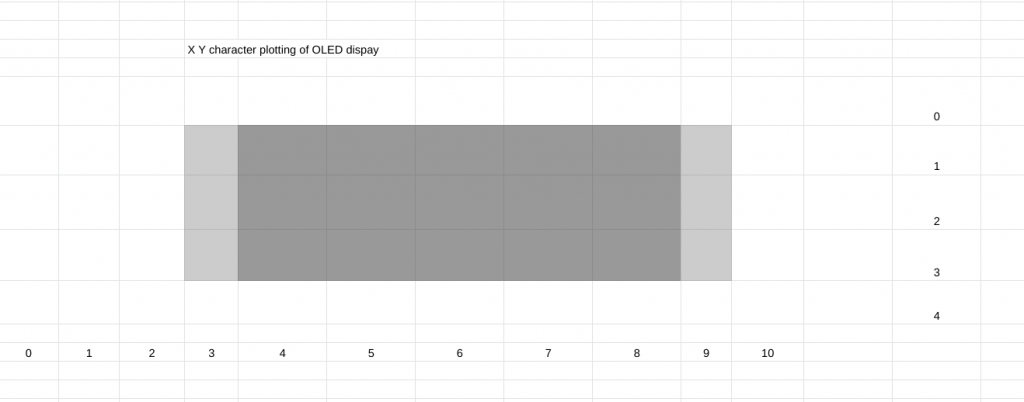
Through the experimentation and adjusting the x,y values we were able to discover the coordinates for visible characters on the display. We created a spreadsheet that shows these coordinates:

OLED character plotting diagram
The dark grey squares are the coordinates that a single character in visible. In the light grey squares the characters get trimmed by about 1/3. This effect is visible in in this image:
The code for the OLED display can be found here:
Once we had the screen worked out we went back to the max/min temp code and adjusted it to make it work.
This is the working code:
Micro:bit Radio Chat
Another good bit of code uses the inbuilt radio to let two Micro:bits communicate with each other. The link below is the code for two Micro:bits to send a pattern to each other.
https://drive.google.com/open?id=1-4DMJbEUk5HxTYy5zpfQ8dPNiTIwzgOs
This kind of code can be edited to use Micro:bits as remote controllers.
Going forward
There’s this little wake-able dragon project that looks fun:
Don’t Wake the Dragon! – Making and Coding with the BBC Micro:Bit

